Spectrum Operating Manual - 第148页
S2-9 XX X Se ri es Disp ensi n g Syst em IOM Man ual Troubleshoo ting 7-10 © 2023 Nordson Corporatio n 7.4.10 Syst em Acc uracy Table 7- 10 System Accu racy Symptom Pos sible Cause Recov ery Pr oc ed ures Inaccurate d is…
S2-9XXX Series Dispensing System IOM Manual Troubleshooting
© 2023 Nordson Corporation 7-9
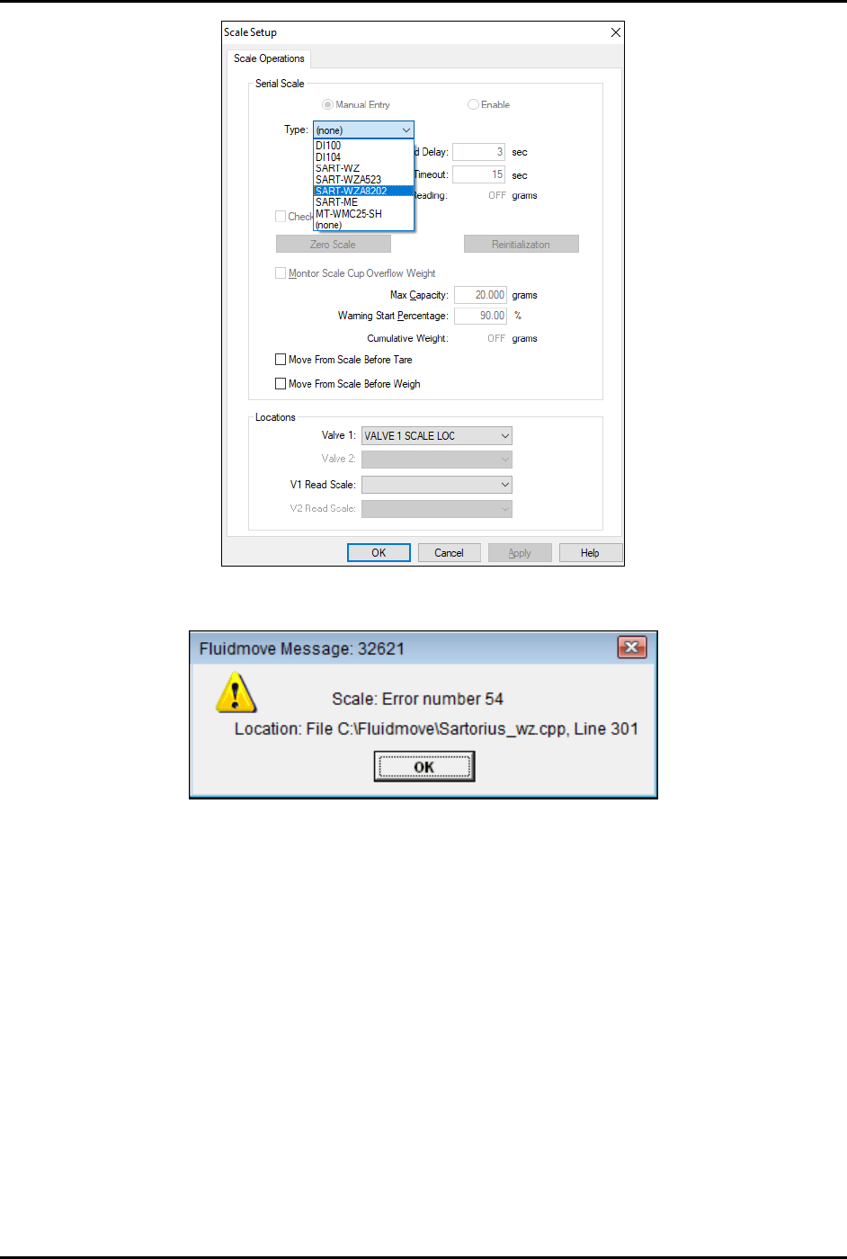
Figure 7-1 Scale Setup Menu
Figure 7-2 Scale Error Message

S2-9XXX Series Dispensing System IOM Manual Troubleshooting
7-10 © 2023 Nordson Corporation
7.4.10 System Accuracy
Table 7-10 System Accuracy
Symptom
Possible Cause
Recovery Procedures
Inaccurate dispensing
Loose camera lens.
Refocus the camera, see 5.4 Focusing the
Camera.
Bad offset routines.
Perform a “Valve Offsets” routine in Fluidmove.
Refer to the Fluidmove User Guide or Fluidmove
Online Help.
Camera needs to be calibrated.
Calibrate the camera, see 5.5 Calibrating the
Camera.
Cal Maps disabled.
Enable Cal Maps. Contact Asymtek Technical
Support.
Bent needle.
Replace the needle. Refer to the applicable valve
manual.
Bad height sensor. Contact Asymtek Technical Support.
Z-head not counterbalanced
properly.
Balance Z-head, see 5.7 Adjusting the Z-Head
Counterbalance Force.
Fiducials not found
Loose camera lens.
Refocus the camera, see 5.4 Focusing the
Camera.
Corrupted vision file.
Re-teach the vision targets or entire program as
necessary.
7.4.11 Substrate Heaters
Table 7-11 Substrate Heater Troubleshooting
Symptom Possible Cause Recovery
Hissing air leak
Missing vacuum hole screw(s). Replace screw(s).
Other pneumatic leaks. Contact Asymtek Technical Support.
Erroneous temperature
display
Wrong display unit. Change display unit to C.
Workpiece part not held
steady
Check for improper open or
plugged vacuum holes.
Remove and install screws as applicable.
Vacuum does not start or
fails to work properly
System has low or no air
pressure.
1. Verify air is connected to facility air supply.
2. Set main air regulator to approximately 620 kPa
(90 psi).
Hot plate does not heat
Set Point (SP) value below
Present Value (PV).
Change the SP value within the Heater Controls
window. Refer to the Fluidmove User Guide or
Fluidmove Online Help.
Disconnected heater.
Verify the heater cable connections are securely
attached to the correct ports.
Hardware or software failure. Contact Asymtek Technical Support.
Blown fuse on the
conveyor/heater controller.
Check the fuses by the heater power connections
on the conveyor controller and replace if
necessary, see 8.16 Replacing Fuses.

S2-9XXX Series Dispensing System IOM Manual Troubleshooting
© 2023 Nordson Corporation 7-11
7.4.12 Tactile Sensor
Table 7-12 Tactile Sensor Troubleshooting
Symptom Possible Cause Recovery
During setup routine,
error indicates that the
tactile sensor is already
engaged
Tactile sensor cap is stuck in the
down position.
Visually inspect the sensor cap for fluid buildup. If
there is fluid, clean the cap, see 7.4.13.1 Tactile
Sensor Error. If there is no fluid, contact Asymtek
Technical Support.
The tactile sensor signal can be tested from the
Fluidmove Tools > IO menu. Select IO and inputs.
Locate the tactile cap signal display and monitor its
state as the cap is depressed and released. If the
state does not change, the precision switch may
have failed.
Needle-to-height-sensor
offset is inaccurate
Fluid build-up on probe tip or
tactile sensor cap may have
caused inaccurate height sensor
calibration.
1. Clean probe tip/tactile sensor cap, see 7.4.13.1
Tactile Sensor Error.
2. Perform a “Valve Offsets” routine in Fluidmove.
For assistance, refer to the Fluidmove User
Guide or Fluidmove Online Help.
7.4.12.1 Tactile Sensor Error
If you receive a tactile sensor error, the following procedure may remedy the error.
NOTE If you continue to receive tactile sensor errors after performing the following procedure,
contact Asymtek Technical Support.
To remedy a tactile sensor error (Figure 7-3):
1. Gently lift the tactile sensor cap off of the tactile sensor.
2. Use isopropyl alcohol and a soft cloth to remove any residual fluid from around the
circumference of the cap, the tactile sensor opening and the sensor tip.
3. Replace the tactile sensor cap.
4. In the Main Window, click on
Tools.
5. In the Tools Window, click on
I/O Test.
6. Click on
Dispenser.
7. Locate the I/O for the tactile sensor.
8. Gently press down on the tactile sensor and make sure that the bit toggles
ON and OFF.
If the bit does not toggle
ON and OFF, the tactile sensor may need to be replaced.
Contact Asymtek Technical Support.