Spectrum Operating Manual - 第166页
S2-9 XX X Se ri es Disp ensi n g Syst em IOM Man ual Parts Replacement 8-14 © 2023 Nordson Corporatio n 8.12.2 R epla cing the M echanical/Tact ile Height Sen sor Probe To replace the h ei ght s ensor p robe ( Figure 8- …
S2-9XXX Series Dispensing System IOM Manual Parts Replacement
© 2023 Nordson Corporation 8-13
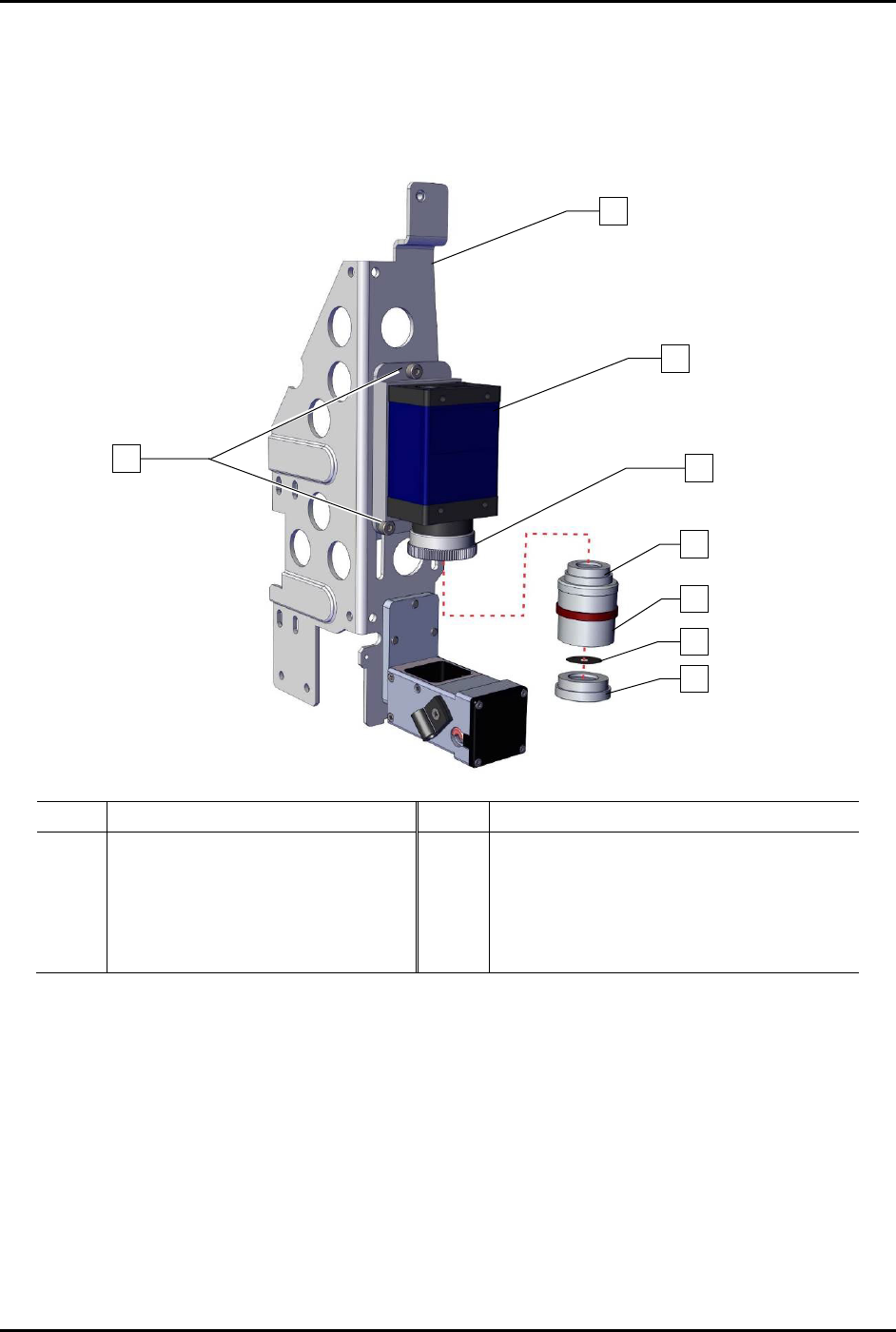
10. Install the lower section onto the middle section by hand-tightening clockwise
(Figure 8-10).
11. Install the lens onto the 2x optical lens clockwise until hand tightened.
12. Focus the camera, see 5.4 Focusing the Camera.
Item
Description
Item
Description
1
Bracket
5
Upper Section
2
Screw (Third screw is located
opposite of lower left screw)
6 Middle Section
3 Camera (Item 55) 7 Aperture Disk
4
2x Optical Lens
8
Lower Section
Figure 8-10 Replacing the Camera Lens
1
3
4
7
6
5
8
x3
2
S2-9XXX Series Dispensing System IOM Manual Parts Replacement
8-14 © 2023 Nordson Corporation
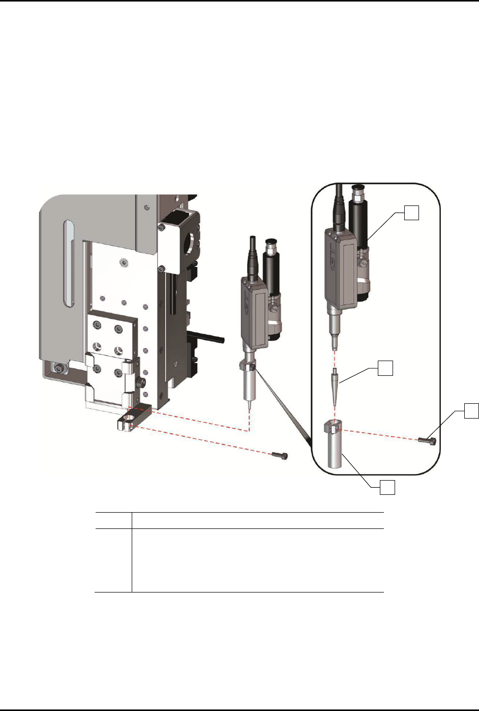
8.12.2 Replacing the Mechanical/Tactile Height Sensor Probe
To replace the height sensor probe (Figure 8-11):
1. Pull the height sensor probe down.
2. Loosen the height sensor locking screw on the front of the height sensor assembly and
remove the height sensor sleeve.
3. Remove the height sensor probe by turning it counterclockwise and sliding it out.
4. Install a new height sensor probe and turn it clockwise to tighten it.
5. Replace the height sensor sleeve and tighten the locking screw.
Item
Description
1 Height Sensor Assembly (Item 54)
2 Height Sensor Probe
3 Height Sensor Probe Locking Screw (front)
4 Height Sensor Sleeve
Figure 8-11 Replacing the Height Sensor Probe
1
2
3
4
S2-9XXX Series Dispensing System IOM Manual Parts Replacement
© 2023 Nordson Corporation 8-15
8.13 Replacing Components Inside the Dispensing Area
Door
Tools and Materials Needed:
• Hex Key Set (Item 59)
• Torque Wrench
• Adjustable Wrench
WARNING! Ensure the dispensing system has been completely shutdown before attempting
to remove or install any panel, electrical component, or pneumatic component.
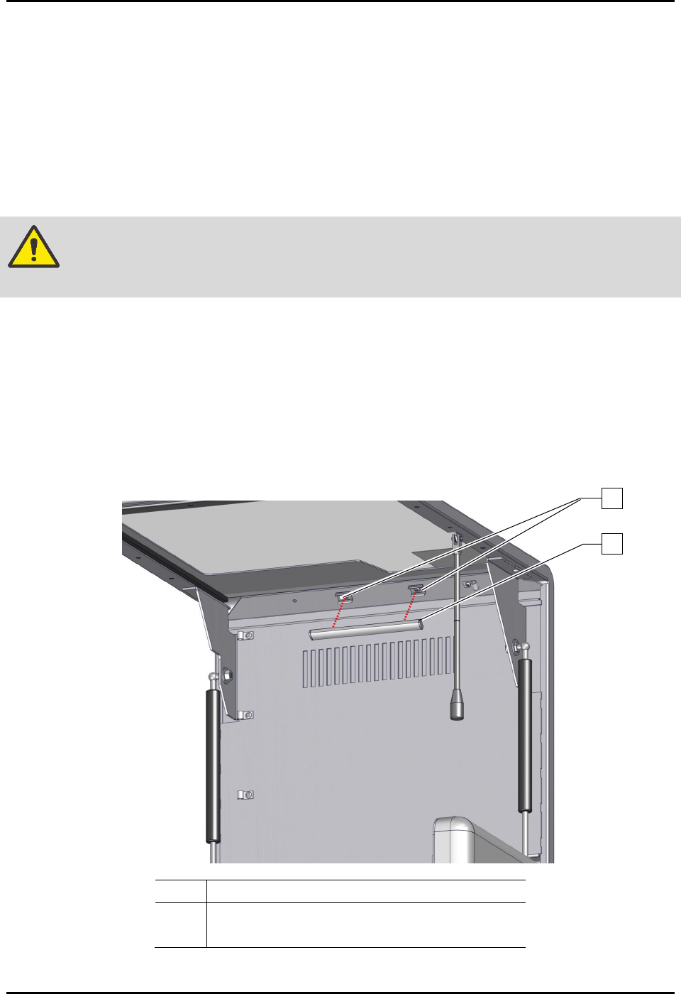
8.13.1 Replacing the LED Light
To remove the LED light (Figure 8-12):
1. Perform a service shutdown, see 2.14 Service Shutdown.
2. Open the dispensing area door.
3. Disconnect the electrical connection to the LED light.
4. Remove the LED light from the LED lens clips.
Item
Description
1 LED Lens Clips
2 LED, Lens, Clips, Kit, 12V, 6” (Item 45)
Figure 8-12 Replacing the LED Light (Wiring Not Shown for Clarity)
1
2