Spectrum Operating Manual - 第172页
S2-9 XX X Se ri es Disp ensi n g Syst em IOM Man ual Parts Replacement 8-20 © 2023 Nordson Corporatio n 8.13.4 Replacing the Interlock Switch To remove the interlock s witch ( Figure 8- 17 ): 1. Perform a service shutd o…
S2-9XXX Series Dispensing System IOM Manual Parts Replacement
© 2023 Nordson Corporation 8-19
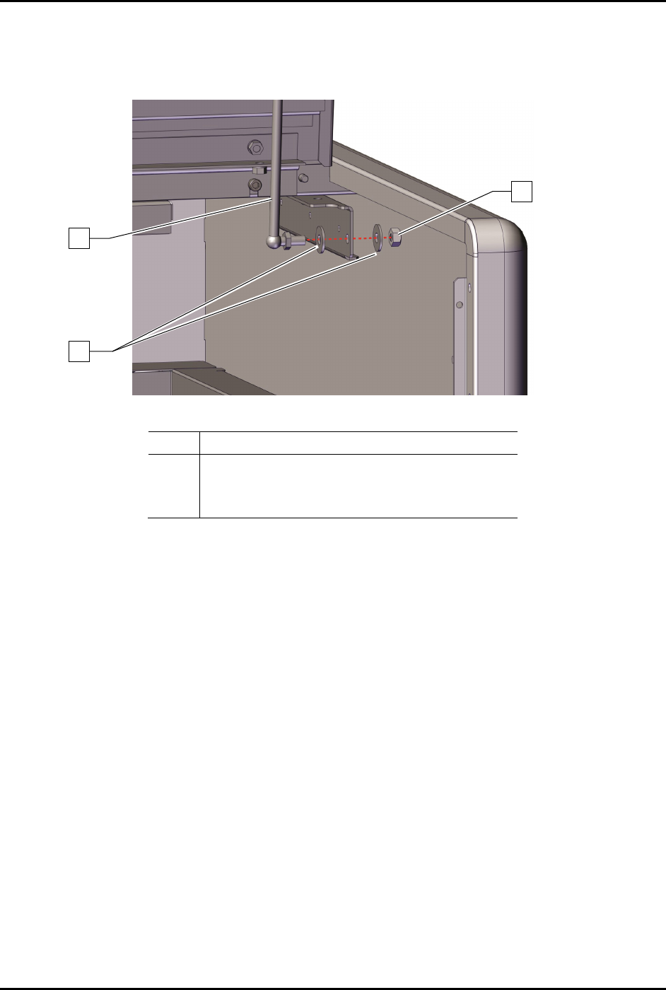
4. Remove the hex nut and two (2) washers securing the gas spring to the dispensing system
(Figure 8-15).
5. Remove the gas spring from the dispensing system (Figure 8-16).
Item
Description
1
2
C-Clips (2)
Standoff (Item 46)
3
Handle (Item 46)
Figure 8-16 Replacing the Lower Portion of the Gas Spring
To install the gas spring and ball joint:
1. Install the hex nut and two (2) washers securing the gas spring to the dispensing area door
(Figure 8-15).
2. Install the hex nut and two (2) washers securing the gas spring to the dispensing system.
(Figure 8-16).
3. Torque the two (2) hex nuts to 9.8 Nm (87 in-lbs) (Figure 8-15 and Figure 8-16).
4. Install a retaining clip, see 8.11.3.1 Replacing the
Gas Spring and Retaining Clip.
5. Close the dispensing area door.
3
2
1
S2-9XXX Series Dispensing System IOM Manual Parts Replacement
8-20 © 2023 Nordson Corporation
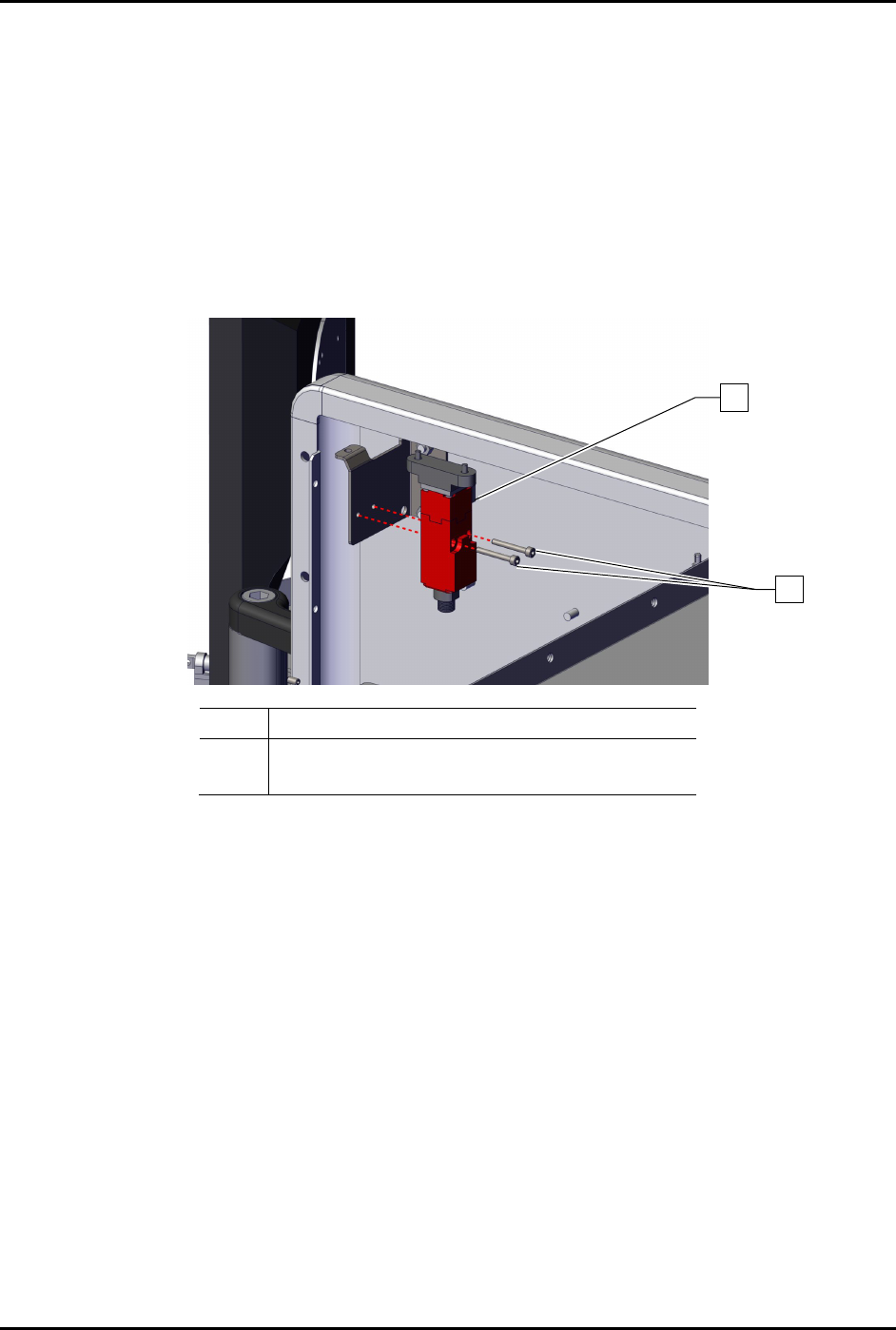
8.13.4 Replacing the Interlock Switch
To remove the interlock switch (Figure 8-17):
1. Perform a service shutdown, see 2.14 Service Shutdown.
2. Open the dispensing area door.
3. Disconnect the electrical connection to the interlock switch.
4. Remove the two (2) screws securing the interlock switch to the dispensing system.
5. Remove the interlock switch.
Item
Description
1
2
Switch, Interlock, AB “ELF” (Item 47)
Screws (2)
Figure 8-17 Replacing the Interlock Switch (Wiring Removed for Clarity)
To install the interlock switch (Figure 8-17):
1. Install the interlock switch to the dispensing system with two (2) screws.
2. Torque the two (2) screws to 1.4 Nm (12 in-lbs).
3. Connect the electrical connection to the interlock switch.
4. Close the dispensing area door.
1
2
S2-9XXX Series Dispensing System IOM Manual Parts Replacement
© 2023 Nordson Corporation 8-21
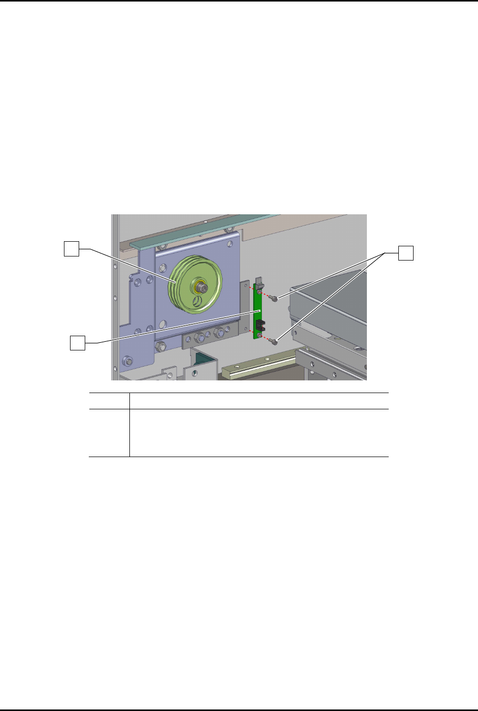
8.13.5 Replacing the Home Sensor
To remove the home sensor (Figure 8-18).
1. Perform as service shutdown, see 2.14 Service Shutdown.
2. Open the front latch.
3. Remove the left y-axis cable cover, see 6.9.2 Y-Axis Cable Cover.
4. Remove the y-home sensor cable from the home sensor.
5. Remove the two (2) screws securing the home sensor to the dispensing system.
The home sensor is located on the left front pulley assembly.
6. Remove
the home sensor from the dispensing system.
Item
Description
1 Left Front Pulley Assembly (Item 11)
2
PCA, Home Sensor EXT (Item 48)
3 Screws (2)
Figure 8-18 Replacing the Home Sensor
To install the home sensor (Figure 8-18)
1. Install the two (2) screws securing the home sensor to the dispensing system.
2. Torque the two (2) screws to 0.39 Nm (3.45 in-lbs).
3. Install the Y-home sensor cable to the home sensor.
4. Install the Y-axis cable cover, see 6.9.2 Y-Axis Cable Cover.
5. Close the dispensing area door.
3
1
2