Spectrum Operating Manual - 第188页
S2-9 XX X Se ri es Disp ensi n g Syst em IOM Man ual Parts Replacement 8-36 © 2023 Nordson Corporatio n To install the pressure gaug e: 1. Install the pressure gauge with fitting through the pneumatics panel assembly. …
S2-9XXX Series Dispensing System IOM Manual Parts Replacement
© 2023 Nordson Corporation 8-35
To install the regulator (Figure 8-25):
1. Install the regulator from the rear of the pneumatic panel assembly.
2. Hand tighten the regulator nut onto the regulator securing the regulator to the pneumatic
panel assembly.
3. Connect the pneumatic connection to the regulator.
4. Install the pneumatics panel, see 8.14.1 Removing and Installing the Pneumatics Panel.
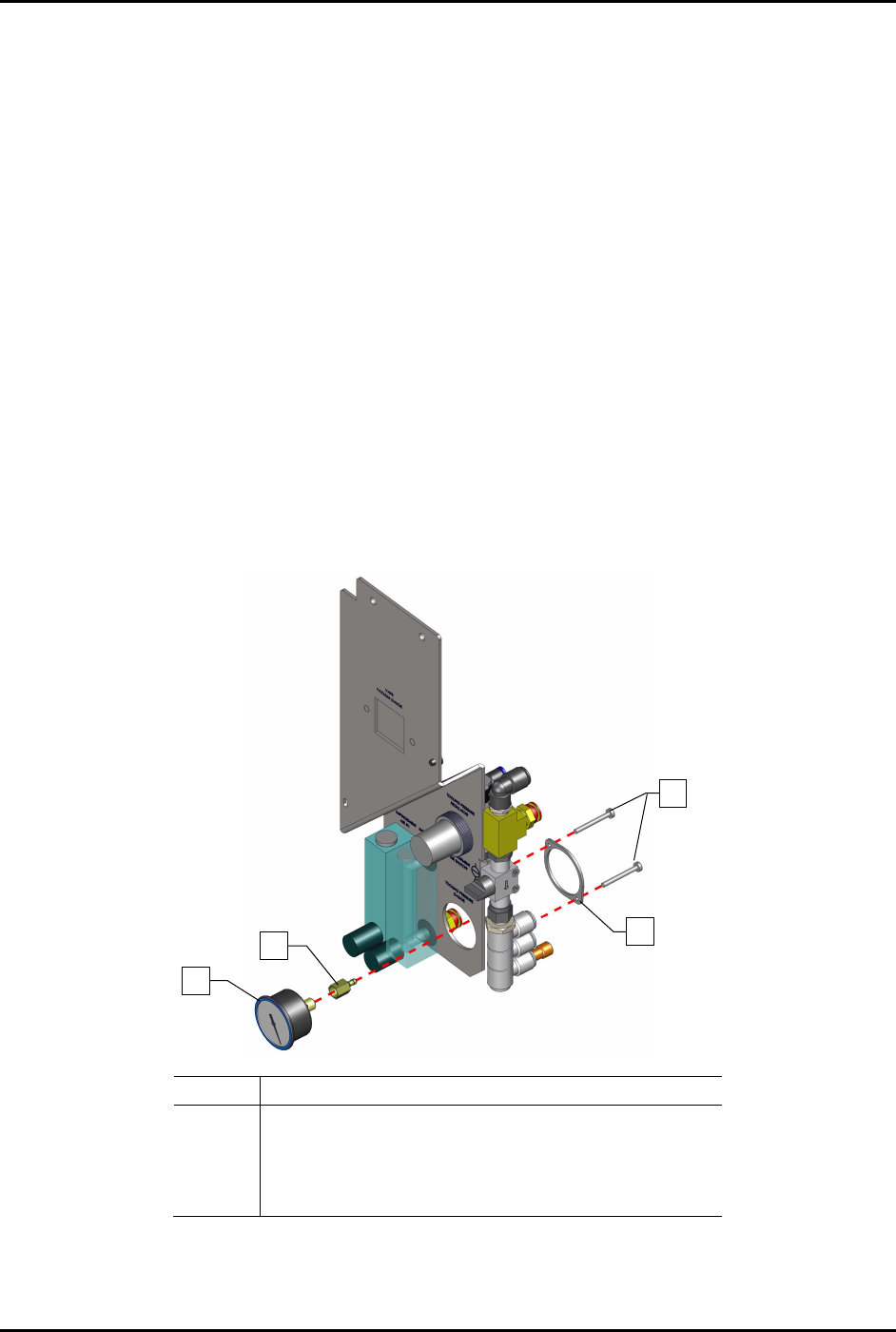
8.16.3 Replacing the Pressure Gauge
To remove the pressure gauge (Figure 8-26):
1. Remove the pneumatics panel, see 8.14.1 Removing and Installing the Pneumatics Panel.
2. Disconnect the pneumatic connection from the regulator.
No
te the connection location.
3. From the rear of the pneumatics panel assembly, remove the two (2) screws and mounting
ring securing the pressure gauge to the regulator panel.
4. Remove the pressure gauge with fitting from the pneumatics panel assembly.
Item
Description
1
Gauge, 0-100 PSI/KPA (Item 50)
2 Fitting, 1/8 FPT X .170 Item 51)
3
Gauge Mounting Ring
4 Screws (2 for each gauge)
Figure 8-26 Replacing the Pressure Gauge
4
3
2
1
S2-9XXX Series Dispensing System IOM Manual Parts Replacement
8-36 © 2023 Nordson Corporation
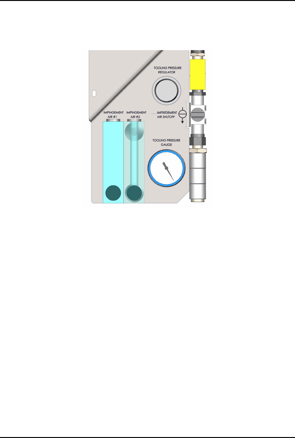
To install the pressure gauge:
1. Install the pressure gauge with fitting through the pneumatics panel assembly.
Orient the pressure gauge as shown in Figure 8-27.
Figure 8-27 Pressure Gauge Orientation
2. From the rear of the pneumatics panel assembly, install the mounting ring over the pressure
gauge and install two (2) screws securing the pressure gauge to the pneumatics panel
assembly (Figure 8-26).
3. Connect the pneumatic connection to the pressure gauge.
4. Reattach the pneumatics panel to the dispensing system, see 8.14.1 Removing and Installing
the Pneumatics Panel.
S2-9XXX Series Dispensing System IOM Manual Parts Replacement
© 2023 Nordson Corporation 8-37
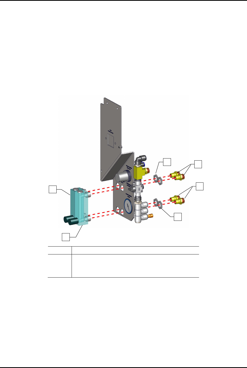
8.16.4 Replacing the Impingement Flowmeters
To remove the impingement flowmeters (Figure 8-28):
1. Remove the pneumatics panel, see 8.14.1 Removing and Installing the Pneumatics Panel.
2. Disconnect the pneumatic connection from the regulator.
Note the connection location.
3. From the rear of the pneumatics panel assembly, remove the four (4) fittings and four (4)
nuts.
4. Remove the two (2) flowmeters.
Item
Description
1
Flowmeter
2
Nuts (2 each gauge)
3
Fittings (2 each gauge)
Figure 8-28 Replacing the Impingement Flowmeters
To install the flowmeters (Figure 8-28):
1. Insert the flowmeters into the pneumatics panel assembly and install the four (4) nuts and
four (4) fittings.
2. Torque to 9.8 Nm (87 in-lbs).
3. Reconnect the pneumatic connections.
4. Reattach the pneumatics panel to the dispensing system, see 8.14.1 Removing and Installing
the Pneumatics Panel.
2
1
1
2
3
3