Spectrum Operating Manual - 第196页
S2-9 XX X Se ri es Disp ensi n g Syst em IOM Man ual Parts Replacement 8-44 © 2023 Nordson Corporatio n 8.17.6 Replacing the Servo Power Supply To remove the power supply (Fig ure 8-34): 1. Perform a service shutd own, s…
S2-9XXX Series Dispensing System IOM Manual Parts Replacement
© 2023 Nordson Corporation 8-43
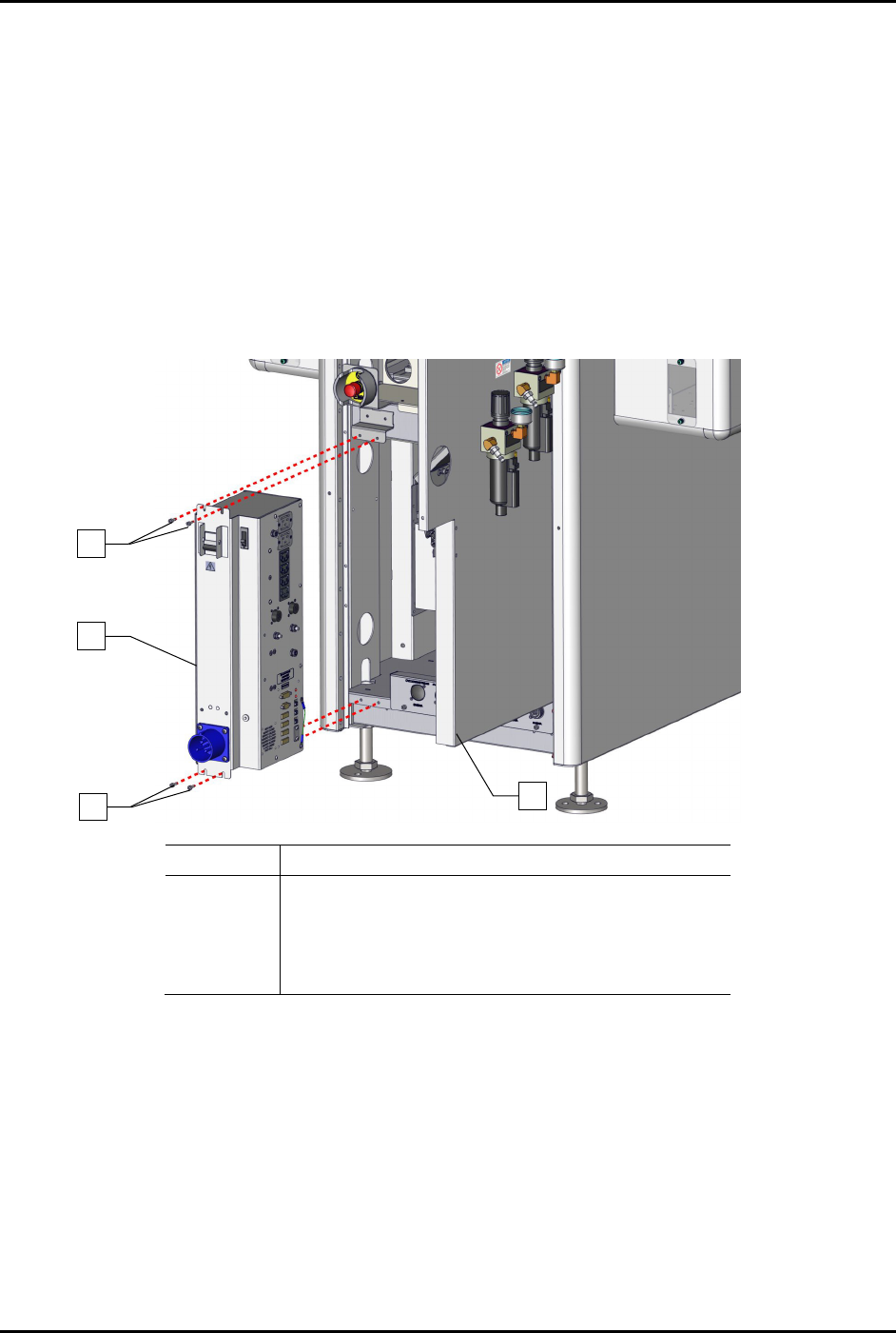
8.17.5 Replacing the Power Manager
To remove the power manager (Figure 8-33):
1. Perform a service shutdown, see 2.14 Service Shutdown.
2. Open the rear door of the dispensing system.
3. Disconnect all electrical connections to the power manager.
4. Disconnect the grounding wire from the power manager to the dispensing system.
5. Remove the four (4) screws securing the power manager to the dispensing system.
6. Remove the power manager.
Item
Description
1 Screws (4)
2 Assy, 30A CM Power Manager C31 (Item 22)
3 Rear Door Panel
Not Shown Grounding Wire
Figure 8-33 Replacing the Power Manager
To install the power manager (Figure 8-33):
1. Install the four (4) screws securing the power manager to the dispensing system.
2. Connect the grounding wire to the dispensing system.
3. Connect all electrical connections to the power manager.
4. Close the rear door of the dispensing system.
2
1
1
3
S2-9XXX Series Dispensing System IOM Manual Parts Replacement
8-44 © 2023 Nordson Corporation
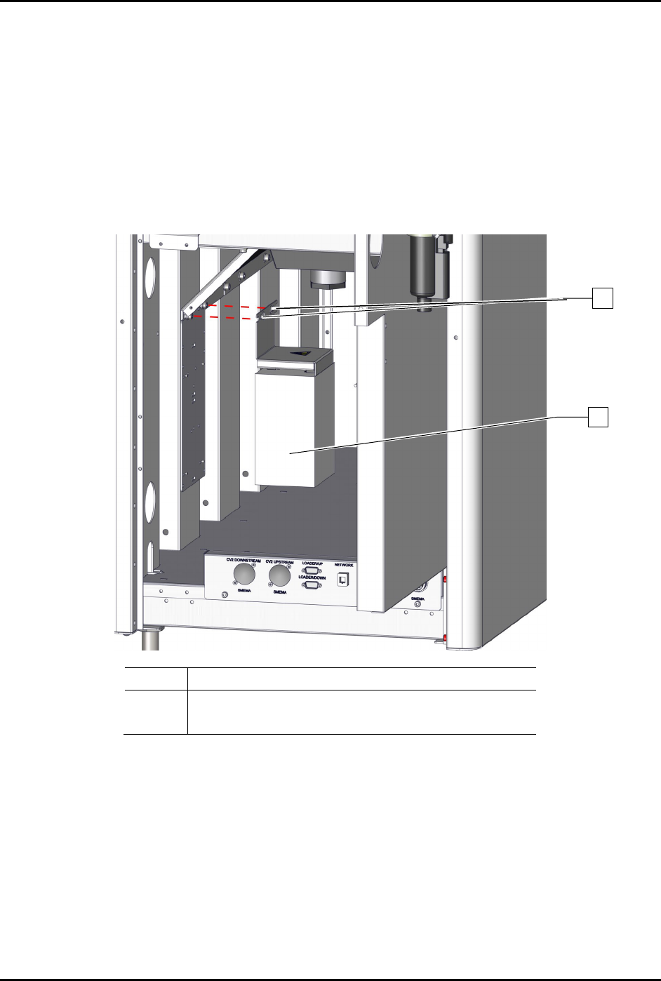
8.17.6 Replacing the Servo Power Supply
To remove the power supply (Figure 8-34):
1. Perform a service shutdown, see 2.14 Service Shutdown.
2. Open the rear door of the dispensing system.
3. Disconnect all electrical connections to the servo power supply.
4. Loosen the two (2) screws securing the servo power supply to the dispensing system.
5. Remove the servo power supply.
Item
Description
1 Screws (2)
2
Power Supply, 600W, 48 VDC, Switch (Item 52)
Figure 8-34 Replacing the Servo Power Supply
To install the servo power supply (Figure 8-34):
1. Tighten the two (2) screws securing the servo power supply to the dispensing system.
2. Torque the two (2) screws to 1.4 Nm (12 in-lbs).
3. Connect all electrical connections to the servo power supply.
4. Close the rear door of the dispensing system.
2
1
S2-9XXX Series Dispensing System IOM Manual Parts Replacement
© 2023 Nordson Corporation 8-45
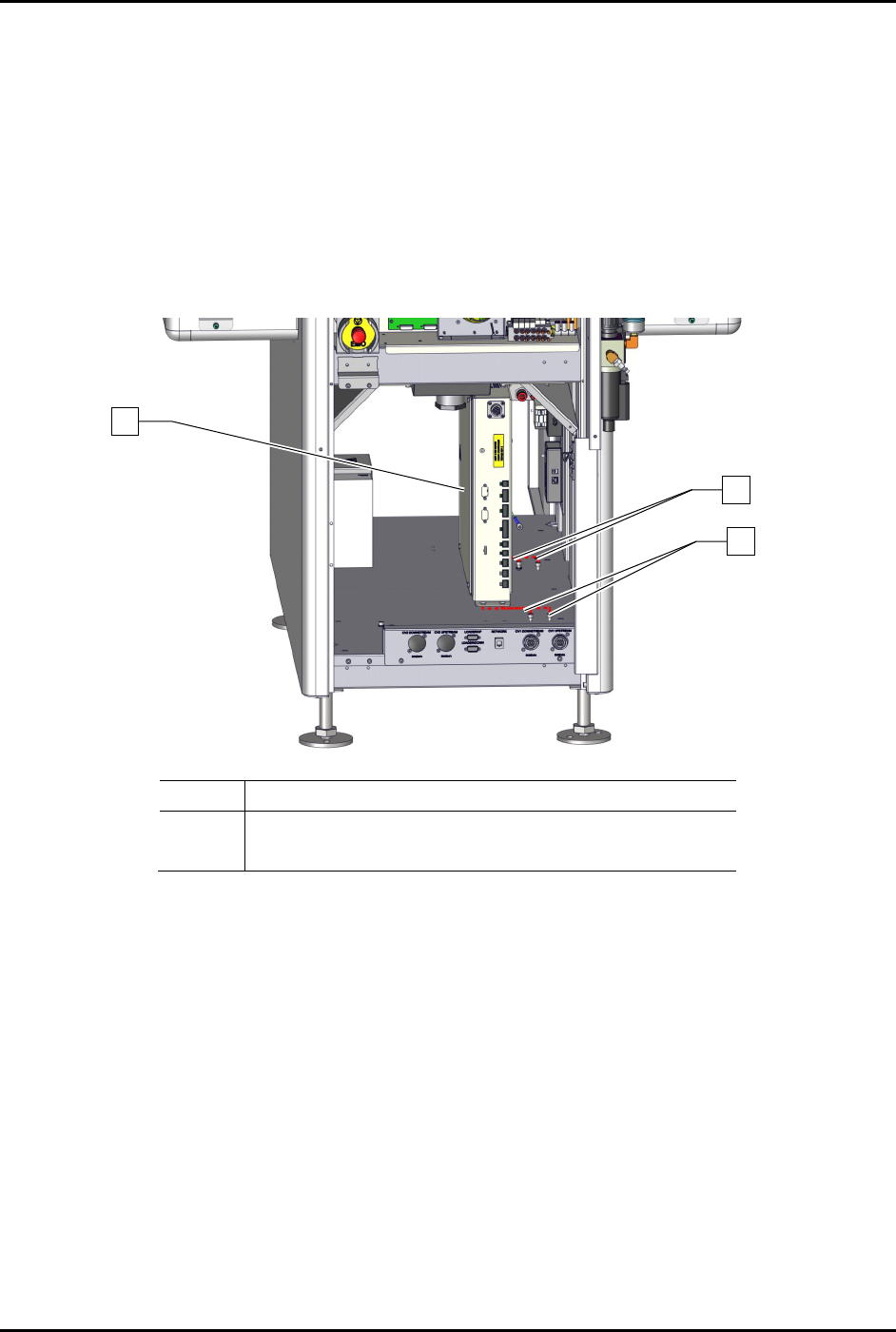
8.17.7 Replacing the Conveyor Controller
To remove the conveyor controller assembly (Figure 8-35):
1. Perform a service shutdown, see 2.14 Service Shutdown.
2. Open the rear door of the dispensing system.
3. Disconnect all electrical connections to the conveyor controller.
4. Loosen the four (4) screws securing the conveyor controller to the dispensing system.
5. Remove the conveyor controller.
Item
Description
1 Base, Conveyor Controller w/USB (Item 53)
2 Screws (4)
Figure 8-35 Replacing the Conveyor Controller
To install the conveyor controller (Figure 8-35):
1. Tighten the four (4) screws securing the conveyor controller to the dispensing system.
2. Connect all electrical connections to the conveyor controller assembly.
3. Close the rear door of the dispensing system.
1
2
2