Spectrum Operating Manual - 第199页
S2-9 XXX Se ri es Dispensing Sys te m IOM Man ual Parts Replacement © 2023 Nordson C orpor ation 8-47 8.18.2 Board Mount ed Fuses This circu it boa rd fuse is mounted i n a ho lder on the m ain PWA and P iezo D ispense H…
S2-9XXX Series Dispensing System IOM Manual Parts Replacement
8-46 © 2023 Nordson Corporation
8.18 Replacing Fuses
Use the following procedures to remove and replace a fuse.
Tools and Materials Needed
• ESD Grounding Strap
• Replacement Fuse (Table 8-5)
• Small Flat Head Screwdriver (Item 59)
• Phillips Screwdriver (Item 59)
WARNING! Always replace fuses with fuses of identical rating and size. Failure to do so may
not protect components from damage.
WARNING! This procedure should be performed by a trained service technician only.
8.18.1 Replacement Fuses
There are approximately ten (10) replaceable fuses (Table 8-5) on the standard S2-9XXX Series
Dispensing System. This number may vary depending on system configuration. All fuse locations are
clearly labeled.
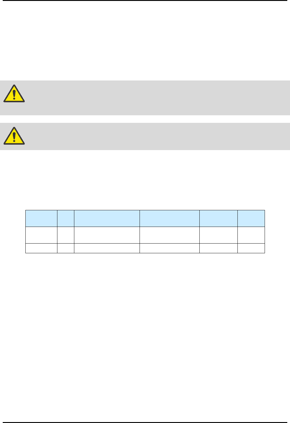
Table 8-5 Replaceable Fuses
Item
Number
Qty. Location Rating Size
Mount
Type
Item 59 2
Main PWA (1)
PWA, PDHC (1)
5A, 125V 280 mil Board
Item 59 8 Heater Relay Module 6.3A, 250V, SLOW 5 x 20 mm Panel
S2-9XXX Series Dispensing System IOM Manual Parts Replacement
© 2023 Nordson Corporation 8-47
8.18.2 Board Mounted Fuses
This circuit board fuse is mounted in a holder on the main PWA and Piezo Dispense Head Controller
(PDHC) located in the back of the dispensing system. The fuse protects the PDHC from damage caused
by electrical overloads from +24V supplied circuits.
To remove and replace the main PWA and PDHC board-mounted fuses:
1. Perform a service shutdown, see 2.14 Service Shutdown.
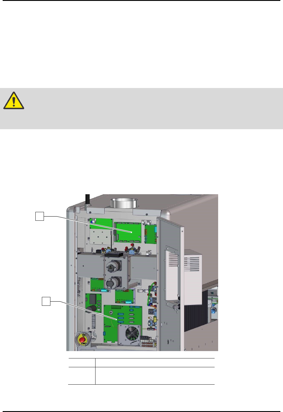
2. Open the rear dispensing area door and locate the board (Figure 8-36).
CAUTION! The circuit board and its components are susceptible to damage by electrostatic
discharge. Observe all ESD protection protocols while performing this
procedure.
3. Remove and properly dispose of the old fuse.
4. Verify that you will be installing the correct replacement fuse.
5. Trim the leads on the replacement fuse and bend the leads in same orientation as the old 5A
fuse.
6. Properly dispose of the replaced 5A fuse.
Item
Description
1
PWA, PDHC Programmed (Item 37)
2
Main PWA (Item 32)
Figure 8-36 Rear Cabinet
1
2
S2-9XXX Series Dispensing System IOM Manual Parts Replacement
8-48 © 2023 Nordson Corporation
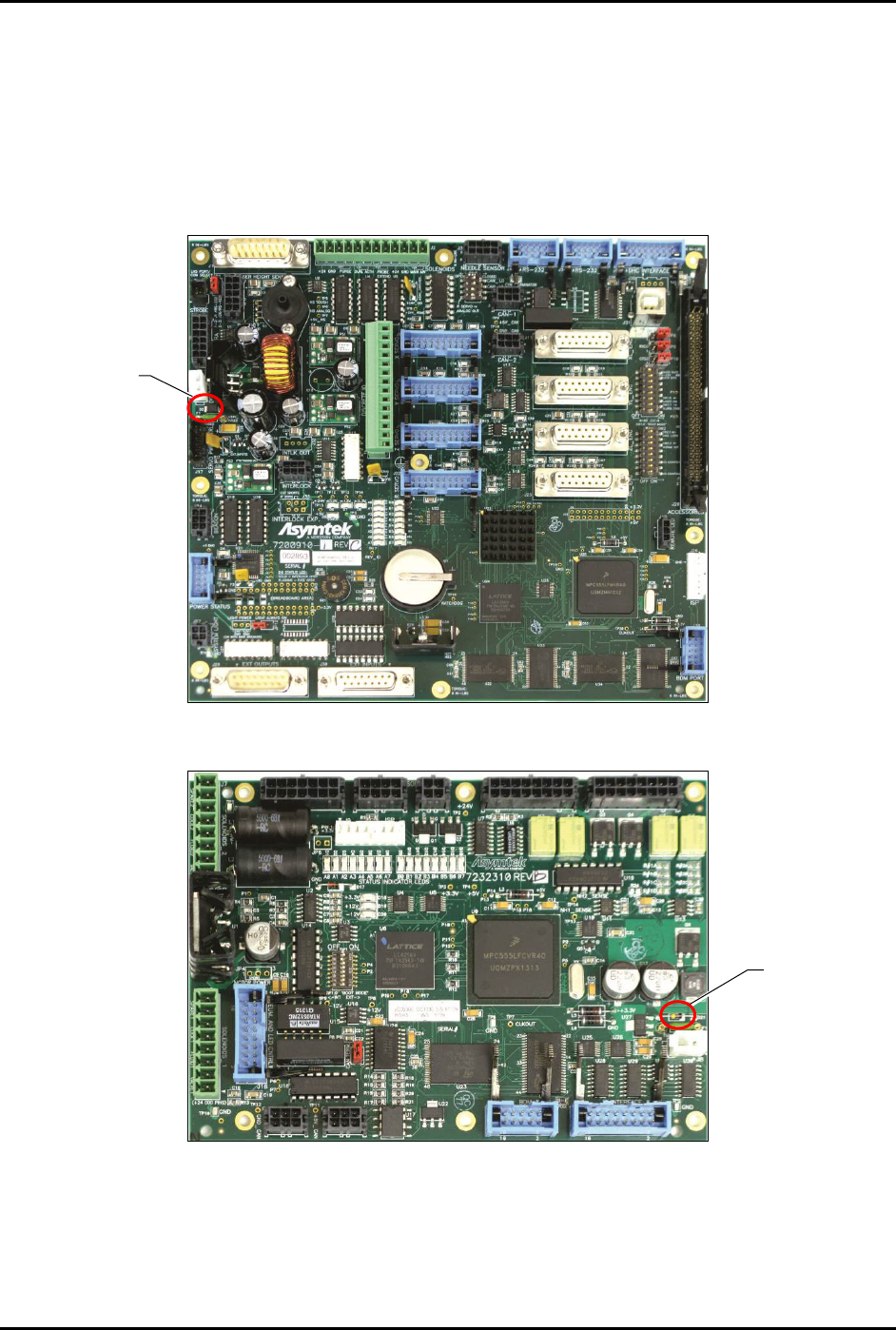
7. Install the new 5A fuse into the fuse holder.
See Figure 8-37 and Figure 8-38 for fuse location.
8. Power on the dispensing system, see 4.3 Powering on the Dispensing System.
9. Verify that the LEDs on the board are now lit.
10. Close the rear dispensing area door.
Figure 8-37 Main PWA Fuse Location
Figure 8-38 PDHC Fuse Location
NOTE The 5A fuses are the only replaceable board fuses. Replacement fuses (Item 59) are
included in Tools & Spares Kit (Item 59).
5A Fuse
5A Fuse