Spectrum Operating Manual - 第21页
S2-9 XXX Se ri es Dispensing Sys te m IOM Man ual Introduction © 2023 Nordson Co rporat ion 1-11 Item Na me Desc ription 1 ULP A Fi lter The Ult r a Lo w Particulate Air (ULPA) Fil ter provid es a d ownward particle - fr…
S2-9XXX Series Dispensing System IOM Manual Introduction
1-10 © 2023 Nordson Corporation
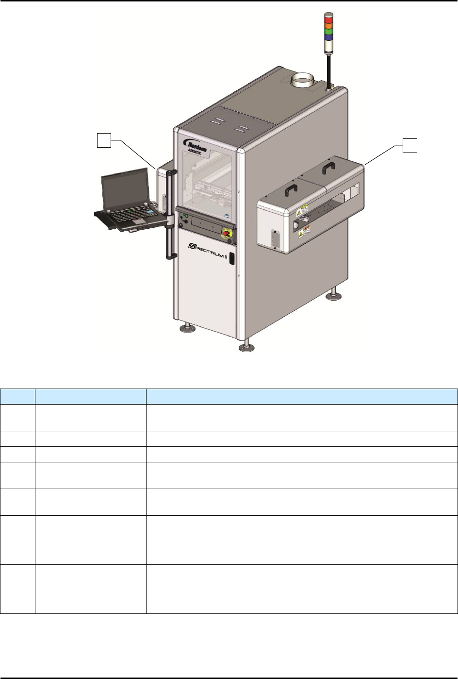
Figure 1-2B S2-9XXX with Optional Pre- and Post-Queue Stations
Item
Name
Description
1 Light Beacon
The Light Beacon is a device that displays system status and can warn
the operator when fault conditions exist.
2 Dispensing Area See 1.11.2 Dispensing Area.
3 Front Panel See 1.11.5 Front Panel.
4 Computer
The dispensing system features a laptop computer which runs the
Fluidmove dispensing software.
5 Exhaust Vent
The Ventilation Exhaust System works in conjunction with the facility
exhaust system to remove excess heat, fumes, or odors.
6 Pre-Queue Station
The optional Pre-Queue Station can be added for higher throughput or
as a buffer station for either single or dual lane configurations. In
addition, the dispensing system can be configured with pre-dispense
heat.
7 Post-Queue Station
The optional Post-Queue Station can be added for higher throughput
or as a buffer station for either single or dual lane configurations. In
addition, the dispensing system can be configured with post-dispense
heat.
Figure 1-3 S2-9XXX Front View
6
7
S2-9XXX Series Dispensing System IOM Manual Introduction
© 2023 Nordson Corporation 1-11
Item Name Description
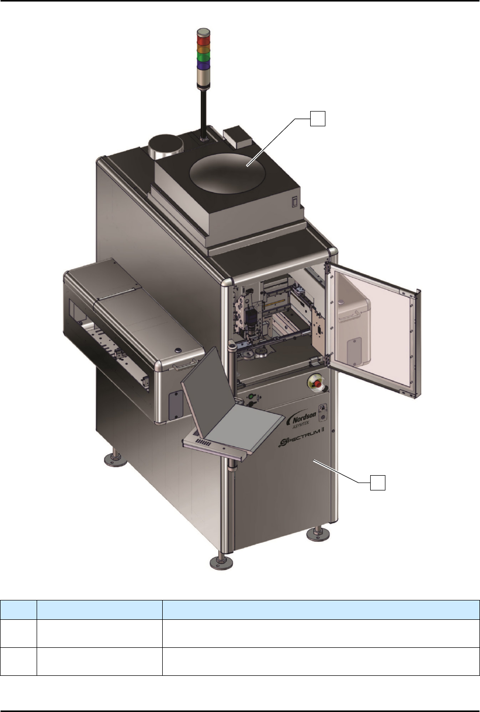
1 ULPA Filter
The Ultra Low Particulate Air (ULPA) Filter provides a downward
particle-free air column within the dispense area.
2 Enclosure
The S2-9XXC Cleanroom system is equipped with a stainless-steel
enclosure.
Figure 1-4 S2-9XXC Cleanroom Configuration with Pre- and Post-Queue Stations
1
2
S2-9XXX Series Dispensing System IOM Manual Introduction
1-12 © 2023 Nordson Corporation
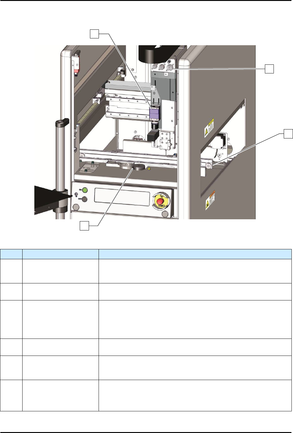
1.9.2 Dispensing Area
Item
Name
Description
1 Vision System
The compact, high resolution, black and white camera and lens are
part of the Vision System. They are mounted on the dispensing head
and are used to view work surfaces.
2
Pneumatic and Electrical
Connections
The bulkhead includes valve, low fluid sensor, and air pressure
connections.
3 Conveyor
The Conveyor transports the workpiece from an upstream system to
the dispensing station and then to a downstream system. All
Conveyors are SMEMA compatible and have adjustable rear rail
width. A Dual Lane Conveyor configuration that allows parallel
processing on two lanes for continuous dispensing is also available.
4 Service Station
The Service Station consists of the dispense tile, tactile needle
sensor, purge station, and scale (Figure 1-5).
Dispensing Valve
(NOT SHOWN)
The Dispensing Valve controls or regulates the flow of material from
a pressurized reservoir, such as a syringe. Devices include valves
and jets.
Laser Height Sensor
(NOT SHOWN)
The Laser Height Sensor is a device that measures substrate height
and sends a signal to the system computer. The height information
is
used to position the dispensing needle at an exact distance above
the workpiece surface.
Figure 1-5 Dispensing Area
2
1
3
4