Spectrum Operating Manual - 第24页
S2-9 XX X Se ri es Disp ensi n g Syst em IOM Man ual Introductio n 1-14 © 2023 Nordson Corpor ation 1.9.4 Scale Sc ale Assemb ly Sc ale Assembly wit h Shutt er (Cle anroom) Ite m Name Description 1 Scale Assembly The sca…
S2-9XXX Series Dispensing System IOM Manual Introduction
© 2023 Nordson Corporation 1-13
1.9.3 Service Station
Item
Name
Description
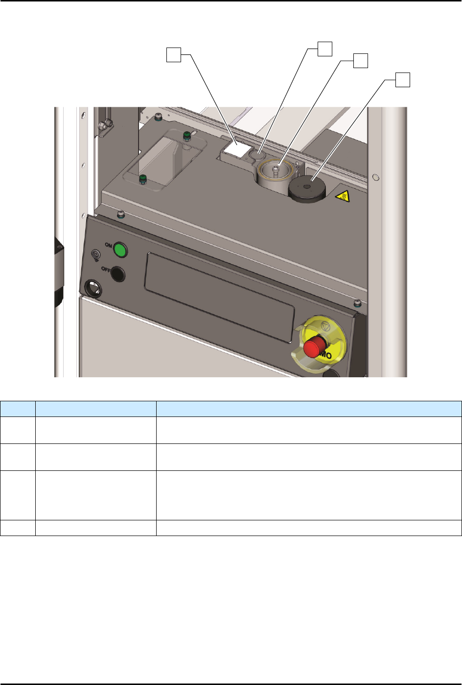
1 Dispense Tile
The Dispense Tile is a ceramic tile dispensed upon during system
offset routines.
2 Tactile Needle Sensor
The Tactile Needle Sensor measures the offset between the
needle/nozzle and the height sensor.
3 Purge Station
The Purge Station consists of a small reservoir that contains a
disposable plastic cup and is attached to a vacuum generator. Air
flowing through the purge boot into the cup removes excess fluid on
the dispensing valve needle/nozzle.
4 Scale See 1.11.4 Scale.
Figure 1-6 Service Station
1
2
3
4
S2-9XXX Series Dispensing System IOM Manual Introduction
1-14 © 2023 Nordson Corporation
1.9.4 Scale
Scale Assembly
Scale Assembly with Shutter (Cleanroom)
Item
Name
Description
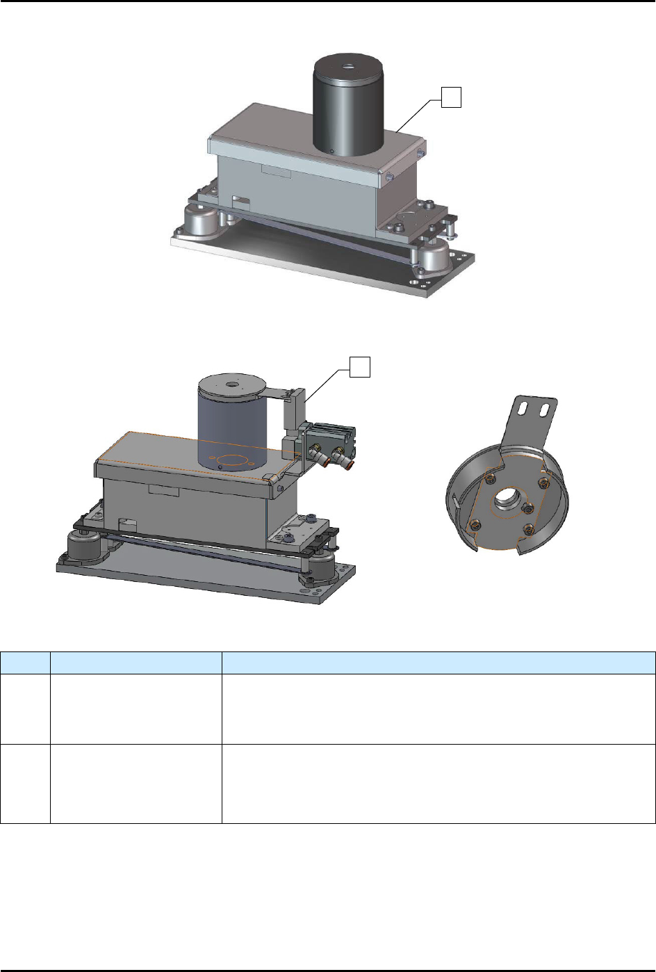
1 Scale Assembly
The scale measures the weight of dispensed fluid and sends the
information to the Fluidmove software for mass flow calibration. The
scale is standard on S2-9XXP systems and an option on S2-9XXX
systems.
2
Scale Assembly with
Shutter (Cleanroom)
The S2-9XXX
Cleanroom configuration has a pneumatically actuated
shutter mechanism built into the scale to prevent fluctuations due to
the ULPA filter System. The shutter only opens when dispensing into
the scale.
Figure 1-7 Scale Assembly
1
2
S2-9XXX Series Dispensing System IOM Manual Introduction
© 2023 Nordson Corporation 1-15
1.9.5 Front Panel
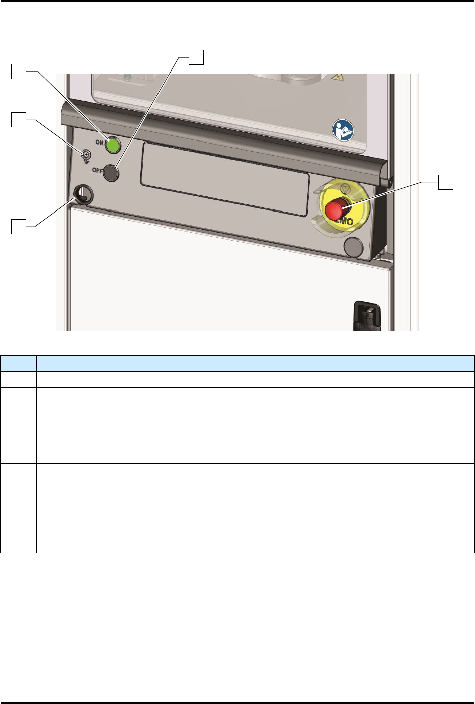
Item Name Description
1 Computer Connection Connects the dispensing system to the laptop computer.
2 Grounding Strap Jack
Grounding straps worn by the operator or technician attach to this
connector. This prevents Electrostatic Discharge (ESD) damage to
workpieces and dispensing system electronics during dispensing
operations and servicing.
3 ON Button
The green ON (l) button illuminates and switches ON power to the
dispensing system mechanics.
4 OFF Button
The black OFF (0) button shuts down the dispensing activity and
vents the air pressure. The computer power remains ON.
5
Emergency Machine Off
(EMO)
Activating the EMO vents all pressure in the pneumatic system, de-
energizes the servo power, and cuts power to all system
components except the computer
. An EMO button is located on the
front and rear of the conformal coating system. See
Section 2 - Safety
for additional information.
Figure 1-8 Front Panel
1
5
4
2
3