Spectrum Operating Manual - 第32页
S2-9 XX X Se ri es Disp ensi n g Syst em IOM Man ual Introductio n 1-22 © 2023 Nordson Corpor ation 1.9.10 Rear Panel Connect ions S2 - 9XXX / S2 - 9XXP S2 - 9XXC Item Name Description 1 CV2 Downst rea m Allows for SMEM …
S2-9XXX Series Dispensing System IOM Manual Introduction
© 2023 Nordson Corporation 1-21
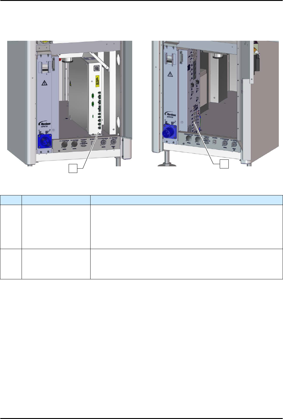
1.9.9 Rear Cabinet
Item
Name
Description
1
Conveyor/Heater
Module
(systems with heat)
Controls all conveyor functions (motors, sensors, pneumatics, etc.). It
receives power from the power manager and supplies AC power to the
substrate heaters in the dispensing area. If your system is equipped
with dual conveyors, there will be two Conveyor/Heater Modules. Note:
if the system does not have heat, it will have a conveyor controller
instead of a Conveyor/Heater Module.
2
Power Manager
(30A shown)
The Power Manager is located inside the rear cabinet. It houses the
main circuit breaker and the main power inlet. It also contains the EMO
circuitry. The EMO buttons, the green ON (I) button, and the black
OFF
(
0
) button are directly connected to the Power Manager.
Figure 1-16 Rear Cabinet
2
1
S2-9XXX Series Dispensing System IOM Manual Introduction
1-22 © 2023 Nordson Corporation
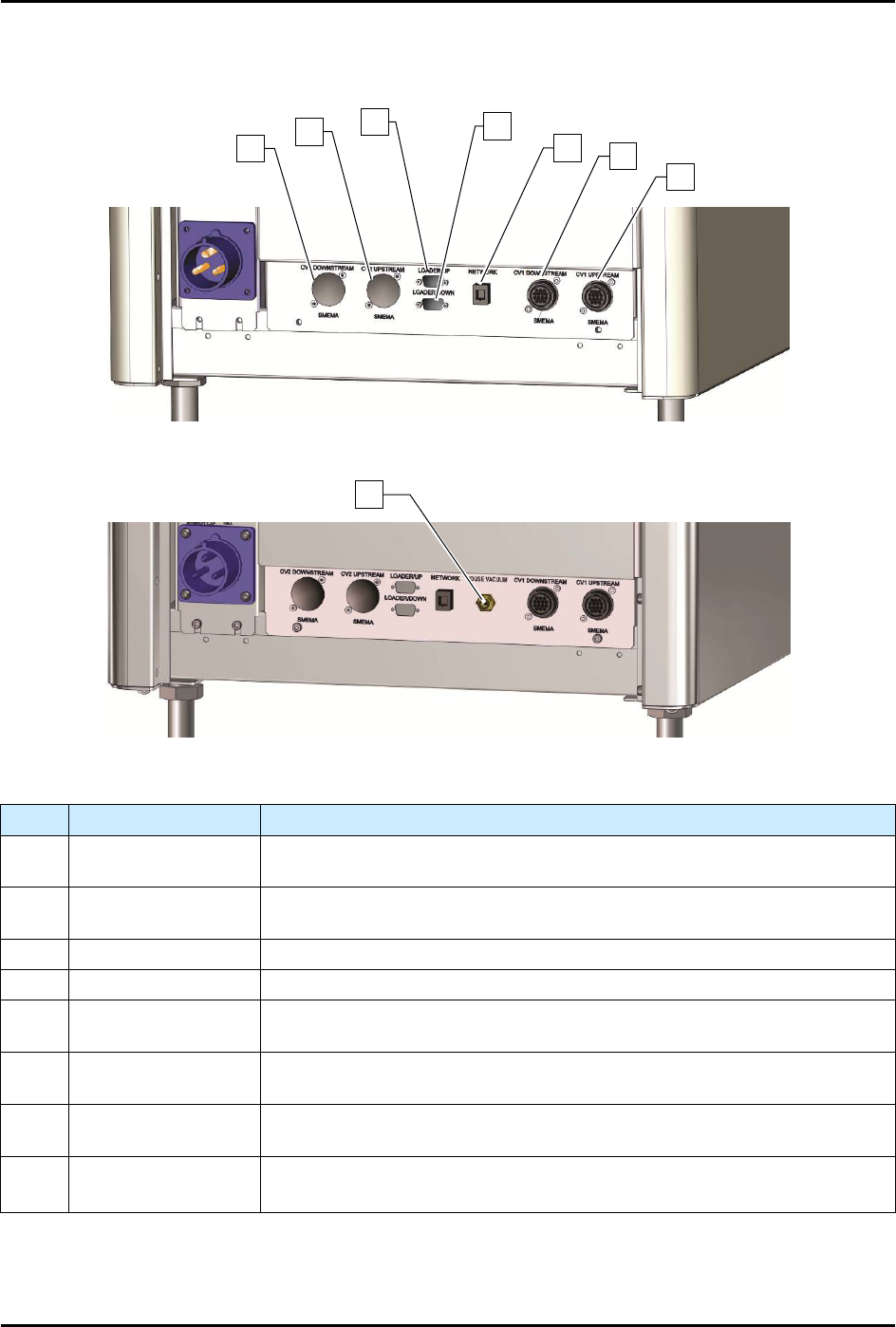
1.9.10 Rear Panel Connections
S2-9XXX/S2-9XXP
S2-9XXC
Item
Name
Description
1 CV2 Downstream
Allows for SMEMA communication between Conveyor 2 and a
downstream machine such as an unloader.
2 CV2 Upstream
Allows for SMEMA communication between Conveyor 2 and an upstream
machine such as a loader.
3 Loader/Up Not used on this machine.
4 Loader/Down Not used on this machine.
5 Network
Allows the dispensing system to communicate with a host computer on a
local area network. Necessary for SECS/GEM functionality.
6 CV1 Downstream
Allows for SMEMA communication between Conveyor 1 and a
downstream machine such as an unloader.
7 CV1 Upstream
Allows for SMEMA communication between Conveyor 1 and an upstream
machine such as a loader.
8
House Vacuum
(S2-9XXC only)
The House Vacuum connection is required for valve purge and to hold
workpieces to the tooling on the cleanroom system.
Figure 1-17 Rear Panel Connections
NOTE CV2 connectors are only present on dual conveyor dispensing systems.
1
2
3
4
5
6
7
8
© 2023 Nordson Corporation 2-1
2 Safety
2.1 Overview
This section is intended to provide basic safety information necessary for operating and servicing the
dispensing system. This section covers the following topics:
• Facility Requirements
• Safety Warning Labels
• System Use
• Residual Safety Risks
• Basic Safety Precautions and Practices
• Emergency Shutdown
• Decommissioning
• Interlock
• Disposal
• Service Shutdown
• Lifting and Transport Precautions
• Laser Radiation • Lockout/Tagout of Electrical and
Pneumatic Energy
• Earthquake Precautions
• Light Beacon
To further optimize safe dispensing system operation, precautions and recommended practices are
included with the procedures throughout this manual.
WARNING! Unsafe equipment conditions can result in personal injury or property damage.
Failure to properly operate and maintain the system in accordance with this
manual could cause the built-in safety features to be ineffective.
NOTE Safety is considered a joint responsibility between the original equipment manufacturer
(Asymtek) and the end-user (owner). All safety precautions and practices should be in
accordance with local regulations and facility policy.
2.2 Facility Requirements
To ensure optimal performance and safety, it is necessary to install the dispensing system in a facility that
meets the necessary requirements, see 9.2 Facility Requirements. If you have any questions, please
contact Asymtek Technical Support.
2.3 System Use
2.3.1 Intended Use
Use of Asymtek equipment in ways other than those described in the documentation supplied with the
equipment may result in injury to persons or damage to property.