Spectrum Operating Manual - 第47页
S2-9 XXX Se ri es Dispensing Sys te m IOM Man ual Safety © 2023 Nordson Co rporat ion 2-15 2.12.1 Emergenc y Shutdown Sit uat ions As a minimum , activ at e the E MO in th e fo llowin g si tuatio ns: W ARNING! In an emer…
S2-9XXX Series Dispensing System IOM Manual Safety
2-14 © 2023 Nordson Corporation
2.12 Emergency Shutdown
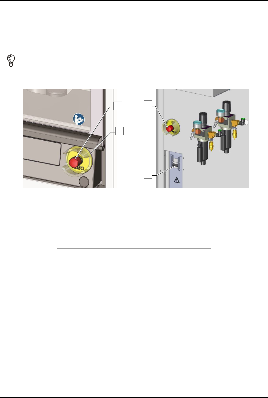
In the event of an emergency or malfunction, press the EMO button. The dispensing system has two EMO
buttons. The EMO buttons are the large red buttons located on the front panel and the rear of the
dispensing system (Figure 2-10). Activating the EMO vents all pressure in the pneumatic system and cuts
power to all components except the laptop computer, the camera, the interior light, and the light beacon.
TIP If the operator or technician is unable to reach the EMO button, the main circuit breaker ,
which is located on the back of the system, can be used for emergency shutdown
(Figure 2-10).
Front Panel Rear View
Item
Description
1 Rear EMO button
2 Front EMO button
3 EMO Guard
4 Main Circuit Breaker
Figure 2-10 EMO/Main Circuit Breaker Locations
2
3
1
4
S2-9XXX Series Dispensing System IOM Manual Safety
© 2023 Nordson Corporation 2-15
2.12.1 Emergency Shutdown Situations
As a minimum, activate the EMO in the following situations:
WARNING! In an emergency, failure to completely shutdown power to the dispensing system
with the EMO can cause serious injury to the user and/or damage to the
dispensing system.
• If anyone is in immediate danger of being injured by moving parts, hazardous materials, or
electrical shock.
• If valuable dispensing system components or the workpieces are in danger of being
damaged. This can include:
- Physical damage to the dispensing valve or workpiece by unexpected dispensing
head movement.
- Electrical damage to the dispensing system.
2.12.2 Emergency Shutdown Recovery
WARNING! Do not restart the dispensing operation until the condition that caused the
emergency shutdown has been corrected. Failure to comply could cause serious
injury to the user and/or serious damage to the dispensing system.
NOTE If the main circuit breaker has been tripped, you will need to restart the dispensing
system, see 4.3 Powering on the Dispensing System.
To recover after an emergency shutdown:
1. Open the dispensing area door and clear the conveyor of all workpieces.
2. Locate and remedy the cause of the emergency shutdown. If necessary, see
Section 7 - Troubleshooting.
3. Close the dispensing area door.
4. Turn the EMO knob clockwise until it pops back into position.
5. Press the
ON (I) button on the front panel.
6. Restart your dispensing program. Refer to the Fluidmove User Guide or Fluidmove Online
Help to load and run a program.
S2-9XXX Series Dispensing System IOM Manual Safety
2-16 © 2023 Nordson Corporation
2.13 Interlock
The interlock is an electronic connection that immediately cuts the power to any motion and pneumatic
actuators. If the dispensing area door is opened during dispensing, the interlock is activated and all
dispensing activity immediately stops to protect the operator from injury.
2.13.1 Interlock Recovery
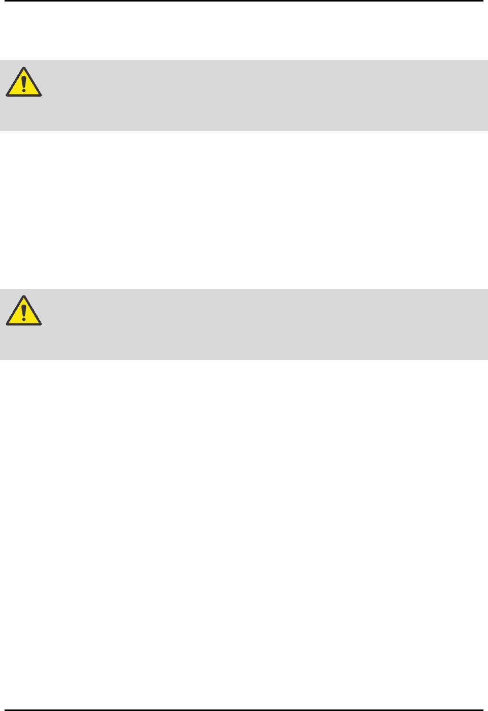
When the interlock is triggered, Fluidmove will display an Interlock Active message (Figure 2-11).
To recover from a shutdown triggered by the interlock:
1. Close the dispensing area door.
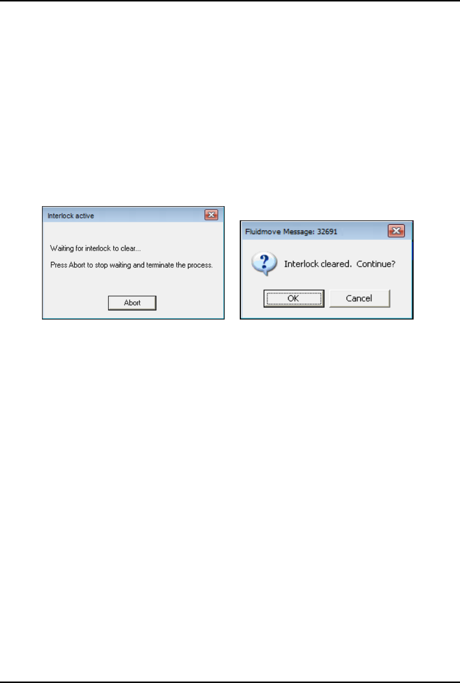
2. When the Fluidmove Message 32691 appears, click
OK to continue dispensing or Cancel to
abort (Figure 2-12).
Figure 2-11 Interlock Active Message
Figure 2-12 Interlock Cleared Message
2.14 Service Shutdown
Before performing any service or parts replacement, the dispensing system should be shutdown
as follows:
1. Shutdown the dispensing system, see 4.8.2 System Shutdown.
2. Perform a “Lockout/Tagout of Electrical and Pneumatic Energy” as described below.
2.15 Lockout/Tagout of Electrical and Pneumatic Energy
Companies may differ in their Lockout/Tagout (LOTO) procedures and requirements, and it is the
responsibility of the end user to determine compliance with local safety procedures. The purpose of any
LOTO effort is to help avoid injury or dispensing system damage due to unexpected energizing of
equipment, start up, or the release of stored energy during repair, maintenance, and operation of
equipment. Situations where LOTO practices may be employed on the dispensing system include:
• Adjusting cables, belts, pulleys, or moving parts
• Servicing bearings or motors
• Troubleshooting, servicing, or replacing electronic components or assemblies
• Troubleshooting, servicing, or replacing pneumatic components or assemblies