Spectrum Operating Manual - 第56页
S2-9 XX X Se ri es Disp ensi n g Syst em IOM Man ual Installation 3-4 © 2023 Nordson Corporatio n 10. Remove bag and plast ic wrap from the mach in e. NOTE Locatio n of packag ing ma terials t o be remo v ed is indicat…
S2-9XXX Series Dispensing System IOM Manual Installation
© 2023 Nordson Corporation 3-3
6. When the four shipping brackets have been removed, slide the forklift forks under the front
of the dispensing system between the levelers (feet). Use the forklift to gently lift the
dispensing system off of the crate.
You may use the shipping crate for future shipping purposes or dispose of according
to local regulations.
Save the shipping brackets. They can be used later for seismically securing the
dispensing system, see 3.11 Anchoring the Dispensing System.
CAUTION! Lift the dispensing system from the front only. Attempting to lift the dispensing
system from the back or sides may cause serious damage. Place forks between
the front feet, making sure that the blades reach from front to back.
WARNING! The dispensing system has a high center of gravity causing sensitivity to tipping.
Use extreme caution when lifting and moving the dispensing system.
7. Move the dispensing system over the location where it will be installed.
NOTE Remove all shrink wrap and packing foam from the system prior to moving it to a
cleanroom. Remove the protective plastic film from the front door, see 3.6 Unpacking the
Dispensing Chamber. If necessary, clean the system thoroughly.
8. Slowly lower the forklift until the dispensing system conveyor rail is at the approximate
height of the mating upstream and downstream equipment.
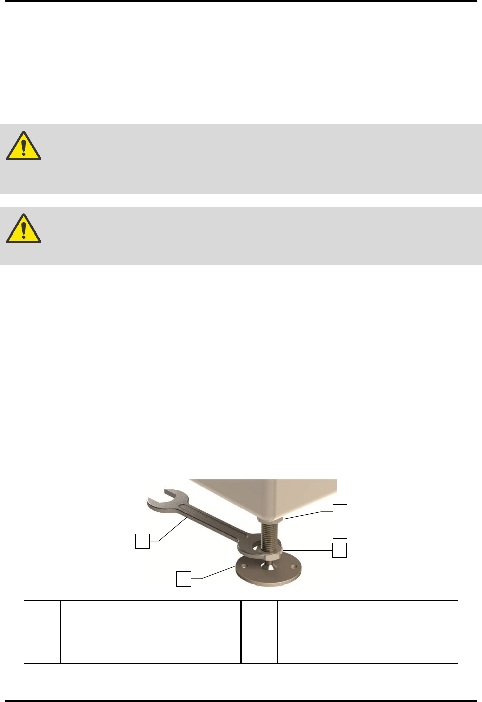
9. Raise or lower each leveler (foot) as follows until they all touch the floor:
a. Loosen the 1 1/2-inch lock nut on the leveler (Figure 3-2).
b. Adjust the 1 1/2-inch post nut to raise or lower each leveler as required.
Turning the post nut clockwise raises the leveler. Turning the post nut
counterclockwise lowers the leveler.
c. Tighten the lock nut finger tight.
Item Description Item Description
1 Lock Nut 4 Leveler (foot)
2 Post 5 1 1/2-inch Wrench
3 Post Nut
Figure 3-2 Adjusting the Levelers
1
5
4
3
2

S2-9XXX Series Dispensing System IOM Manual Installation
3-4 © 2023 Nordson Corporation
10. Remove bag and plastic wrap from the machine.
NOTE Location of packaging materials to be removed is indicated by the presence of
red warning tags.
11. Remove all shrink-wrap and other packing material from the perimeter of the dispensing
system.
3.6 Unpacking the Dispensing Chamber
To unpack the dispensing chamber:
1. Remove all perimeter packaging material from the dispensing area.
2. Remove all tie wraps, tape, foam packing material, and warning tags from the following
areas:
• Dispensing Head
• Conveyor
• Service Station
NOTE Location of packaging materials to be removed is indicated by the presence of
red warning tags. The amount, type, and arrangement of packaging materials
will depend on your system’s configuration.
3. Use a 3 mm hex key to loosen the setscrews on the X- and Y-axis dispensing head stoppers.
4. Remove the stoppers and retain them in a safe place.
5. Remove the shipping bracket and warning tag attached to the Z-head by loosening the
three (3) screws.
Retain bracket and hardware for future shipping purposes.
NOTE The camera is installed and connected at the factory prior to shipping.
6. Remove the tape covering the service station and lid.
7. Remove the front cover by first removing the two screws from the ends of the cover
(Figure 3-3).
8. Lift the cover up and away from the machine.
S2-9XXX Series Dispensing System IOM Manual Installation
© 2023 Nordson Corporation 3-5
Figure 3-3 Removing the Front Cover
9. If the system is equipped with a scale, loosen the strap covering the scale and remove the
warning tag from the scale unit.
NOTE Do not remove the strap. The strap may be needed when moving or shipping
machine.
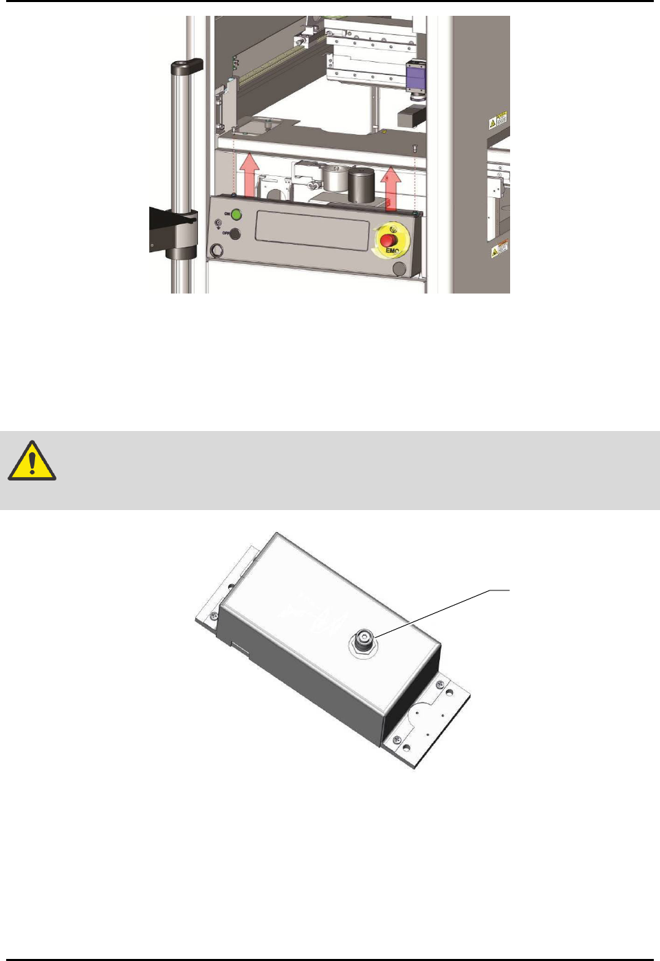
CAUTION! The scale stem is extremely sensitive. Be careful not to hit or apply pressure to
the scale stem (Figure 3-4).
Figure 3-4 Scale Stem
10. Replace the scale cover and reinstall the two mounting screws.
NOTE It is not necessary to level the scale. The scale is leveled to the dispense plane at the
factory and does not need to be leveled again. However, it does need to be recalibrated
after the machine installation is complete, see 5.6 Calibrating the Scale.
11. Remove the tie wraps and warning tag from the lift table(s), if installed.
Scale Stem