Spectrum Operating Manual - 第86页
S2-9 XX X Se ri es Disp ensi n g Syst em IOM Man ual Calibration and Adjus tment 5-10 © 2023 Nordson Corporatio n 5.7 Adjust ing th e Z - Head Counterb alance Force The counterbalance balanc es the load on the Z-axis. It…
S2-9XXX Series Dispensing System IOM Manual Calibration and Adjustment
© 2023 Nordson Corporation 5-9
8. Using gloves or tweezers, place the 50g calibration weight on the pedestal.
9. Replace the scale cover and click
OK.
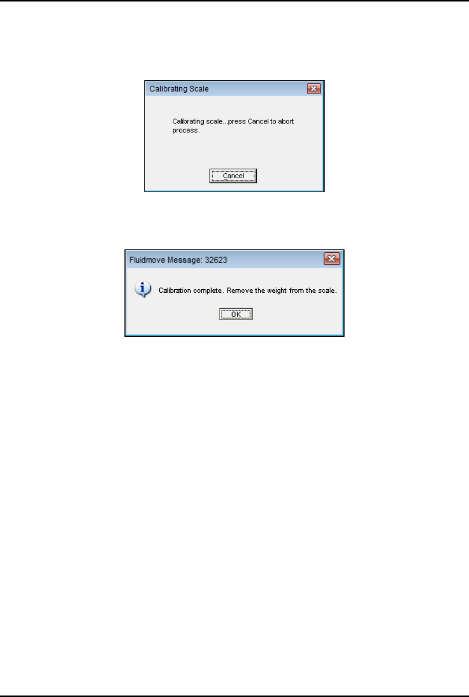
Fluidmove will display the following message (Figure 5-9):
Figure 5-9 Fluidmove Calibrating Scale Message
10. Upon completion, Fluidmove displays the following message (Figure 5-10):
Figure 5-10 Fluidmove Calibration Complete Message
11. Remove the scale cover.
12. Remove the weight from the scale.
13. Click
OK.
14. Replace the cup.
15. Replace the cup and scale cover, wait 10 seconds, then click
OK.
S2-9XXX Series Dispensing System IOM Manual Calibration and Adjustment
5-10 © 2023 Nordson Corporation
5.7 Adjusting the Z-Head Counterbalance Force
The counterbalance balances the load on the Z-axis. It can be set to accommodate various payloads. When
the Z-head is properly balanced, it enables the system to quickly position the Z-axis accurately. This
procedure assumes the valve(s), cabling, and fluid lines are installed.
To adjust the Z-head counterbalance:
1. Power down the system, see 4.8.1 Post-Production Shutdown.
2. Open the dispensing area door.
3. Disconnect the camera and light source cables.
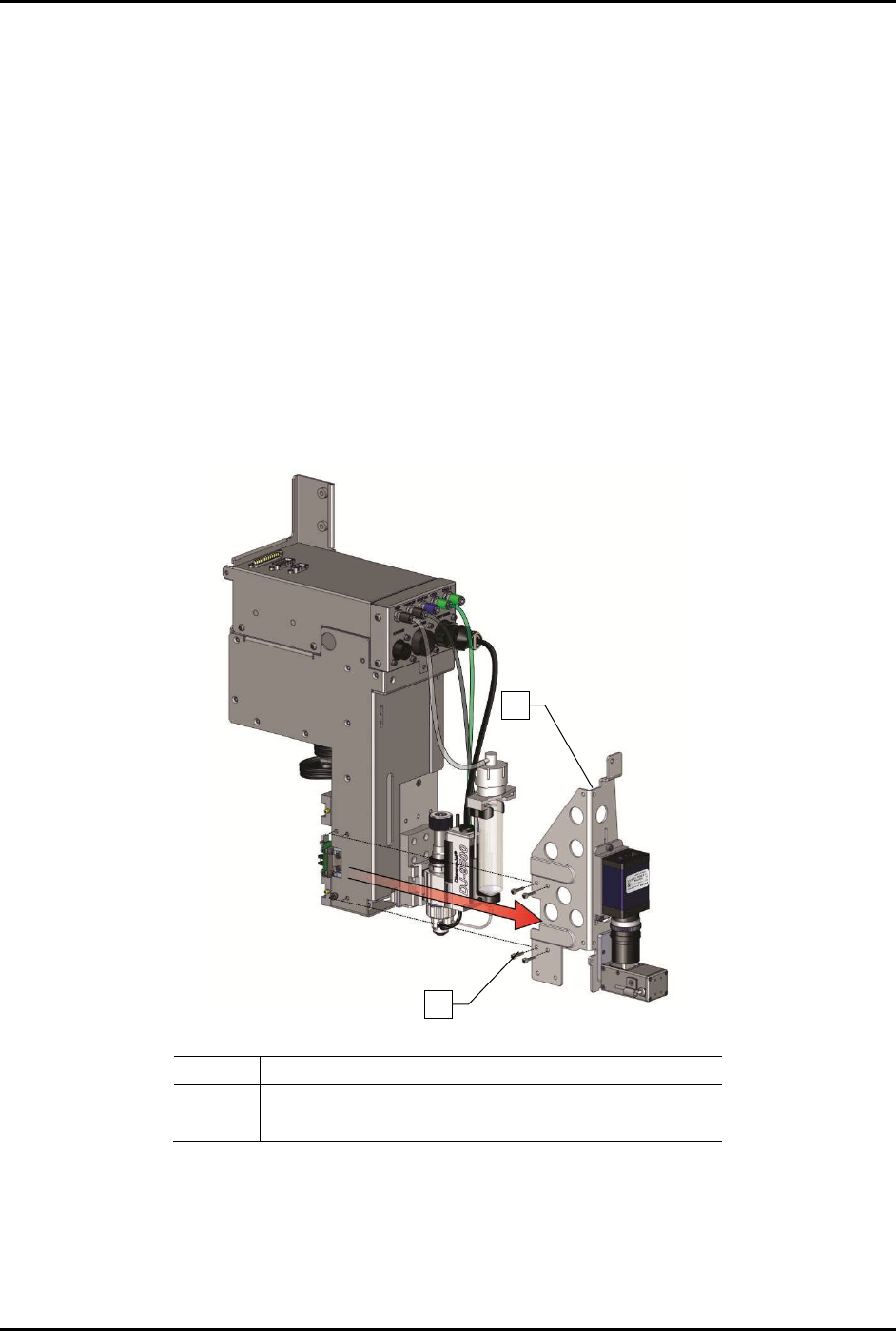
4. Remove the four (4) screws securing the camera and bracket to the Z-head and carefully
remove the camera and bracket (Figure 5-11) and place to the side.
NOTE If the dispensing head is configured with a tactile height sensor assembly, it is
not necessary to remove it to adjust the Z-head counterbalance force.
.
Item
Description
1
Camera Bracket
2
Bracket Mounting Screws
Figure 5-11 Removing the Camera and Height Sensor
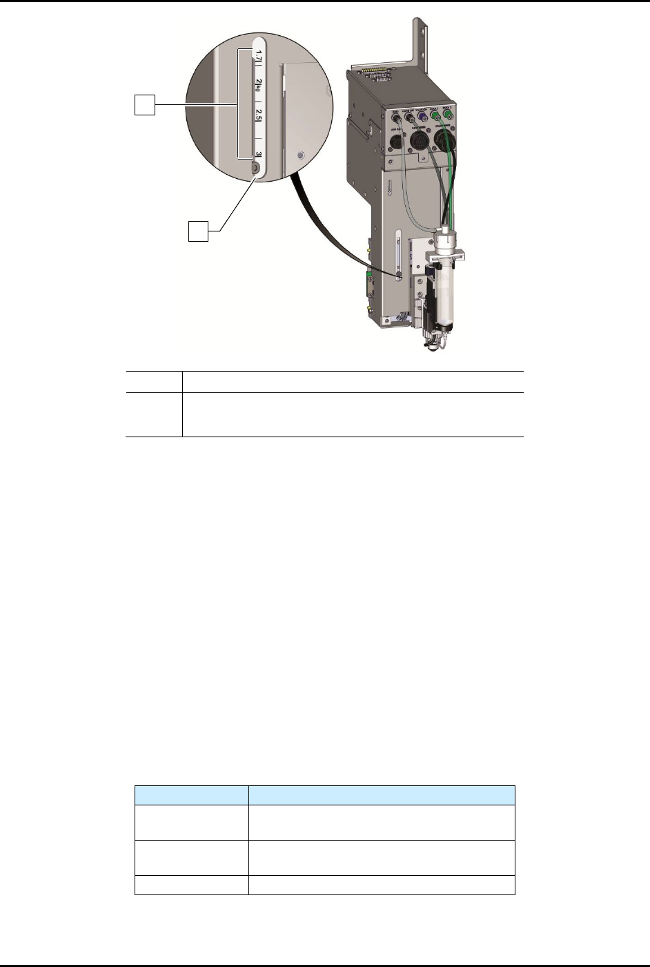
5. Loosen the Z-head counterbalance force adjustment screw (Figure 5-12).
6. Slide the screw assembly to the desired position (Table 5-1).
7. Tighten the Z-head counterbalance force adjustment screw.
1
2
4x
S2-9XXX Series Dispensing System IOM Manual Calibration and Adjustment
© 2023 Nordson Corporation 5-11
Item Description
1 Payload Settings
2 Adjustment Screw
Figure 5-12 Z-Head Counterbalance Force Adjustment
8. Reinstall the camera and bracket.
9. Reconnect the camera and light source cables.
10. Close the dispensing area door.
11. Recalibrate the camera, see 5.6 Calibrating the Scale.
12. Perform a machine offsets procedure.
Refer to the Fluidmove User Guide or Fluidmove
Online Help to perform the offset procedures.
To test counterbalance tension:
1. Place valve on Z-head and move the valve to middle of dispense area.
2. Open the dispensing area door.
The Z-head should not rise or drop more the 6.3 mm (1/4 inch).
3. Readjust tension if necessary.
Table 5-1 Counterbalance Spring Settings
Z-payload (kg)
Typical Applications
0 - 1.7
Standard (i.e. single valve)
Standard with laser height sensor
1.7 - 2.2
Dual action
Dual action with laser height sensor
2.2 - 3
Any custom tooling exceeding 2.2-kg
NOTE The settings in Table 5-1 are for reference purposes only. Certain applications may
require different settings.
2
1