7OM-1625-004_w - 第117页
7OM-1603 3-18 Chapter 3 : 2. Menus for System Setting [5] [Ret] button When this button is Pressed, the "Offset Data" window [6] [Save] button When this button is pressed, the input data is applied. [Cancel] bu…
7OM-1603
Chapter 3 : 2. Menus for System Setting
3-171003-002
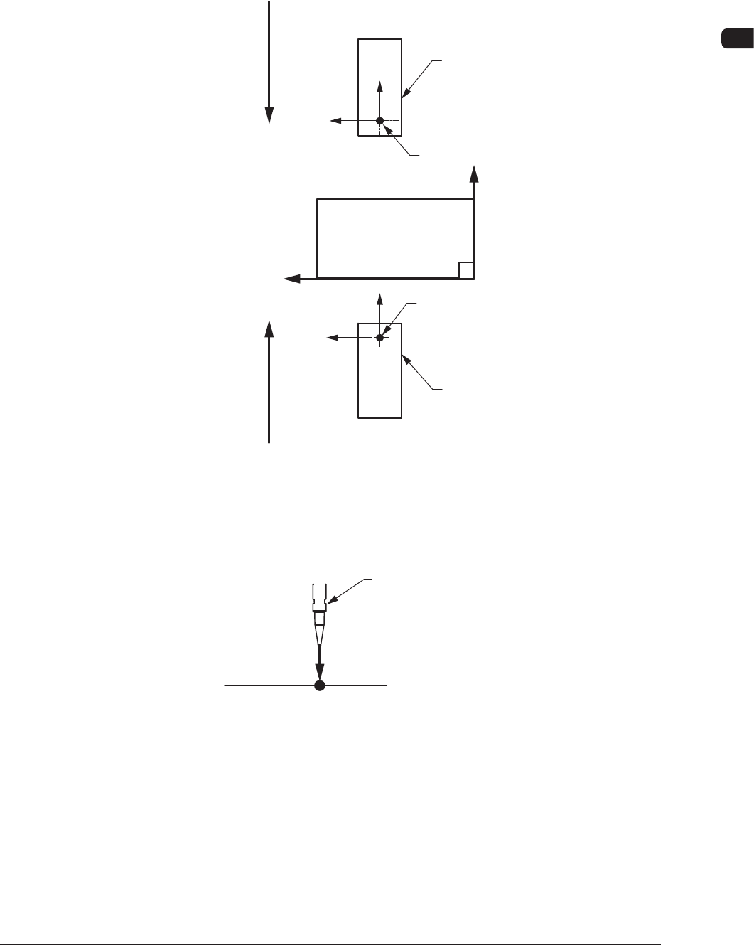
[2] X (Horizontal) and Y (Vertical) [mm]
These offset parameters are used to adjust the positional deviation based on
the design dimensions representing the component pickup position for each
individual feeder slot Nos. (Fdr Nos.).
F211
F111
Rear Feeder
Front Feeder
Front Side of Machine
Y(+)
X(+)
Pickup Position
Pickup Position
Direction of Tape FeedDirection of Tape Feed
F7C17
[3] L (Height) [mm]
Pickup Reference Level
Nozzle
L(+)
F7C18
When a value is entered with a plus (+) sign, the pickup height is reected on
the direction in which the descending stroke of the nozzle will increase.
[4] [Blk Select] button
In this section, the installed multi-layer tray feeder block can be selected.

7OM-1603
3-18
Chapter 3 : 2. Menus for System Setting
[5] [Ret] button
When this button is Pressed, the "Offset Data" window
[6] [Save] button
When this button is pressed, the input data is applied.
[Cancel] button
When this button is pressed, the input data is cancelled and the save data is
returned.
0908-001
7OM-1603
Chapter 3 : 2. Menus for System Setting
3-19
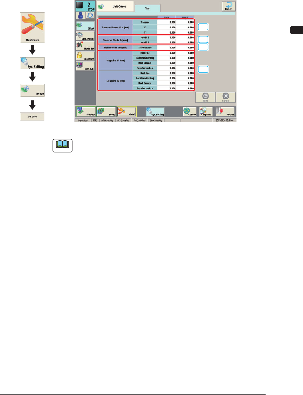
2.1.2 "Unit Offset" Window
When the "Unit Offset" tab is pressed in the "Offset" tab sheet and the "Tray" tab
is further pressed, the following subtab sheet appears.
[1]
[2]
[3]
[4]
"Tray" sub-tab sheet (Multi-Layer Tray Feeder #1 used) F7C19
Note
The displayed tab sheet will look different, depending on which option is
selected.
[1] Traverse Drawer Pos
These offset data is used to adjust the position where a pallet is drawn out by
the traverse shafts.
Traverse [mm]
When a pallet is drawn out, the traverse shafts move as far as the specied
distance where the parameter set in this text box is added.
X [mm] (Horizontal)
The set parameter is added to the beam travel when components are picked
up.
Y
[mm] (V
ertical)
The set parameter is added to the beam travel when components are picked
up.
[2] Traverse Shoot Lv [mm]
L
[mm] (Height)
This offset data is used to adjust the level (height) of the pallet drawing
chute.
Whe
n a level lower than the design height is set, a plus value must be entered
in the text box.
1102-004
Graphic
Development