7OM-1625-004_w - 第55页
7OM-1603 1-14 Chapter 1 : 3. Name of Each Section and Handling 3.1 Elevator Unit The elevator is provided with a mechanism that moves the magazines up and down. The elevator can be loaded with two magazines in which the …
7OM-1603
Chapter 1 : 3. Name of Each Section and Handling
1-13
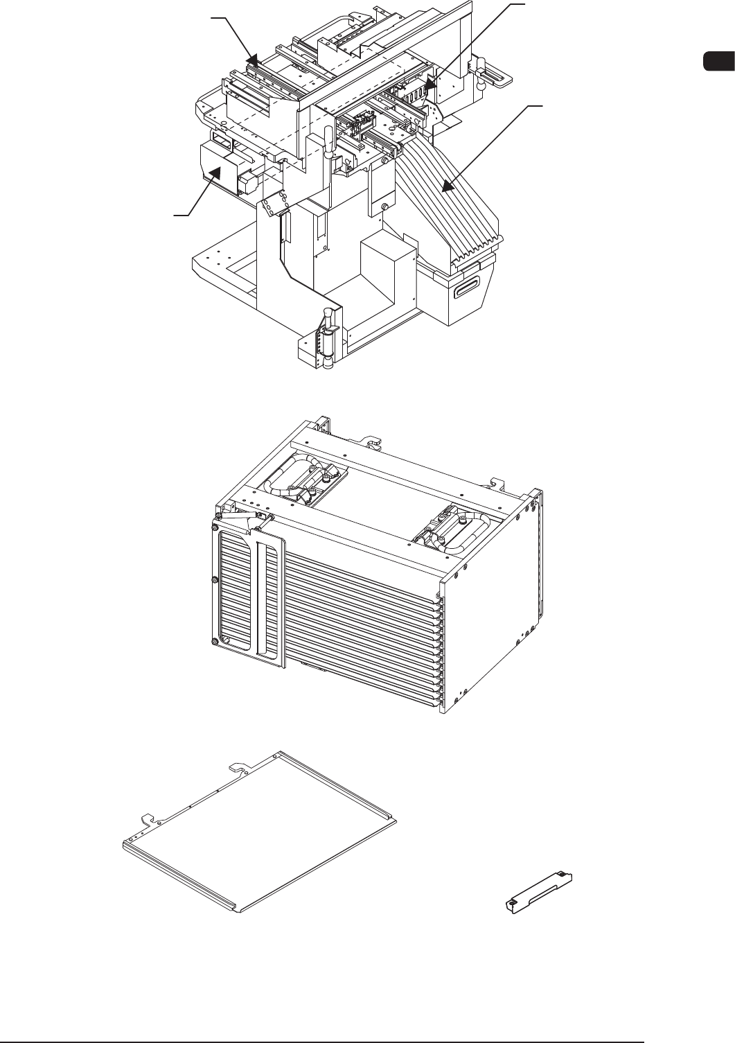
Reel Holder
Slot Section
Traverse Section
Cutter Unit
Traverse Cart F7A2
Magazine (GS-MG100) F7A3
Pallet (GS-MP100)
Tray Fixing Magnet
(GS-MF100)
Pallet and Tray Fixing Magnet F7A4
1003-002
7OM-1603
1-14
Chapter 1 : 3. Name of Each Section and Handling
3.1 Elevator Unit
The elevator is provided with a mechanism that moves the magazines up and
down.
The elevator can be loaded with two magazines in which the pallets are stored.
Each magazine is driven up and down separately.
The trays on the pallets in each magazine can be replenished with components or
the trays on each pallet can be reloaded with components at the specied position.
The magazines can manually be attached to or detached from the elevator.
The magazine loaded on the elevator is clamped with a spring force and positioned
in place.
Also, the elevator unit can be attached to any traverse cart.
WARNING
When the elevator unit is to be moved, pay
attentiontheinclinationoftheooranddifference
inlevel.Iftheoorisinclined10/1000mmormore,
the elevator might fall down, which might cause a
serious accident.
Notice
(a) Do not move the elevator unit with the tray components setup. Doing
so might scatter the tray components around.
(b) When the elevator unit is to be moved, hold the handle attached to
the cover side surface to move it.
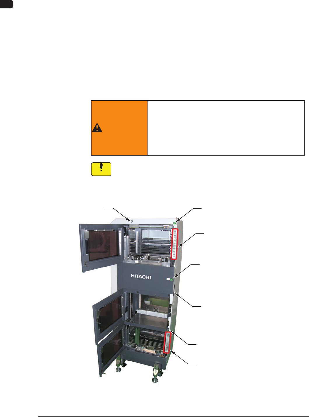
[1] Elevator Power LED
[3] Upper [ALL CHANGE] Button and
Step No. Buttons ([1] through [15])
[3] Lower [ALL CHANGE] Button and
Step No. Buttons ([1] through [15])
[2] Magazine #2 Ready
Ready Switch
Handle
[2] Pallet Change Position Ready
Ready Switch
[2] Magazine #1 Ready
Ready Switch
F7A5
1102-004

7OM-1603
Chapter 1 : 3. Name of Each Section and Handling
1-15
[1] Elevator Power LED
This LED indicates whether or not the elevator is powered.
When the elevator is powered, the LED illuminates.
[2] Ready Switches
(Magazine #1 Ready, Exchange Position Ready, Magazine #2 Ready
Switches)
The machine is equipped with doors and ready switches ("Magazine #1",
"Exchange Position", and "Magazine #2") at each individual magazine
exchange and component supply positions.
The LED of each ready switch indicates the following.
•
When the LED illuminates in green, it indicates that the d
oor is
electromagnetically locked, making it impossible to be opened.
•
When the LED is turned off, it indicates that the door is not locked and
can be opened.
[3]
Step No. Buttons [1] through [15] and [ALL CHANGE] Button
Provided on the inner sides of Magazine #1 and #2 Doors are Step No.
buttons ([1] through [15]) and the [ALL CHANGE] buttons. Each Step No.
can be referred to for checking if a tray is inserted or not.
•
When the LED illuminates in green, it indicates that the step of the
corresponding No. is loaded with components.
•
When the LED is ickering in green, it indicates that the step of the
corresponding No. is short of components.
•
When the LED is turned off, it indicates that no step data is specied in
the pattern program.
When the stage in a component shortage error (ickering LED of the step
No. button) is reloaded with components and the corresponding step No.
button is pressed, the LED illuminates in green.
When several step in component shortage errors are reloaded with
components and the [ALL CHANGE] button is pressed, the LEDs of the
corresponding step Nos. are turned on.
1007-003