SG_FSE_SiplaceHF_HF3_00193900-05_de.pdf - 第70页
1 - 2 S tudent Guide SIPLACE HF/HF3 Inhalt Ausgabe 09/2005 2 3.4.1.1 Spursignale und Nullim pulssignal der Achse . . . . . . . . . . . . . . . . . . . . . . . . . . . 35 3.4.1.2 Nullimpuls des Spursig nalgebers . . . . .…

Student Guide SIPLACE HF/HF3
Ausgabe 09/2005 Inhalt
1
Kapitel
Inhaltsverzeichnis
3 Kommunikation und Steuerung. . . . . . . . . . . . . . . . . . . . . . . . . . . . . . . . . . . . . . . . 3
3.1 Vernetzung . . . . . . . . . . . . . . . . . . . . . . . . . . . . . . . . . . . . . . . . . . . . . . . . . . . . . . . . . . . . . . . . . . . . . 3
3.1.1 Übersicht Kommunikation. . . . . . . . . . . . . . . . . . . . . . . . . . . . . . . . . . . . . . . . . . . . . . . . 3
3.1.2 Übersicht Vernetzung. . . . . . . . . . . . . . . . . . . . . . . . . . . . . . . . . . . . . . . . . . . . . . . . . . . 4
3.2 Netzwerkadresse . . . . . . . . . . . . . . . . . . . . . . . . . . . . . . . . . . . . . . . . . . . . . . . . . . . . . . . . . . . . . . . . 5
3.2.1 Rechner im LAN Netzwerk . . . . . . . . . . . . . . . . . . . . . . . . . . . . . . . . . . . . . . . . . . . . . . . 6
3.2.2 Kommunikation im HF-Bestückautomat . . . . . . . . . . . . . . . . . . . . . . . . . . . . . . . . . . . . . 7
3.2.3 Kommunikation Maschinensteuerung . . . . . . . . . . . . . . . . . . . . . . . . . . . . . . . . . . . . . . 8
3.3 CAN-Bus . . . . . . . . . . . . . . . . . . . . . . . . . . . . . . . . . . . . . . . . . . . . . . . . . . . . . . . . . . . . . . . . . . . . . . . 9
3.3.1 Geschichte des CAN-Bus. . . . . . . . . . . . . . . . . . . . . . . . . . . . . . . . . . . . . . . . . . . . . . . . 9
3.3.2 Allgemeines zum CAN-Bus . . . . . . . . . . . . . . . . . . . . . . . . . . . . . . . . . . . . . . . . . . . . . 11
3.3.2.1 11-Bit Identifier . . . . . . . . . . . . . . . . . . . . . . . . . . . . . . . . . . . . . . . . . . . . . . . . . . 12
3.3.2.2 CAN-Bus-Protokoll . . . . . . . . . . . . . . . . . . . . . . . . . . . . . . . . . . . . . . . . . . . . . . . 12
3.3.2.3 CSMA: Vermeidung von Datenkollision . . . . . . . . . . . . . . . . . . . . . . . . . . . . . . . 13
3.3.2.4 CAN-Bus Arbitrierung. . . . . . . . . . . . . . . . . . . . . . . . . . . . . . . . . . . . . . . . . . . . . 13
3.3.3 CAN-Bus Konzept an der HF-Maschine (bis MA.Nr.xx). . . . . . . . . . . . . . . . . . . . . . . . 15
3.3.4 CAN-Bus Konzept an der HF-Maschine (ab MA.Nr.xx) . . . . . . . . . . . . . . . . . . . . . . . . 16
3.3.5 CAN-Bus Konzept an der HF3-Maschine. . . . . . . . . . . . . . . . . . . . . . . . . . . . . . . . . . . 17
3.3.6 CAN-Bus Struktur mit One Wire Bus am Bsp. der HF3-Maschine. . . . . . . . . . . . . . . . 18
3.3.7 CAN-Bus Prozessorboard C&P Kopf . . . . . . . . . . . . . . . . . . . . . . . . . . . . . . . . . . . . . . 19
3.3.7.1 CAN-Bus gesteuerte Funktionen am C&P Kopf. . . . . . . . . . . . . . . . . . . . . . . . . 19
3.3.8 CAN-Bus Prozessorboard Twin Head . . . . . . . . . . . . . . . . . . . . . . . . . . . . . . . . . . . . . 20
3.3.8.1 CAN-Bus gesteuerte Kopffunktionen am TWIN Head . . . . . . . . . . . . . . . . . . . . 21
3.3.9 CAN E/A-Modul (SLIO) - HF bis MA.Nr. xx . . . . . . . . . . . . . . . . . . . . . . . . . . . . . . . . . 22
3.3.9.2 CAN E/A-Modul Sektor 2, Hauptverteiler . . . . . . . . . . . . . . . . . . . . . . . . . . . . . . 23
3.3.9.3 CAN-E/A im Zwischenverteiler Sektor 4. . . . . . . . . . . . . . . . . . . . . . . . . . . . . . . 25
3.3.10 CAN E/A-Modul (SLIO) - HF ab MA.Nr. xx. . . . . . . . . . . . . . . . . . . . . . . . . . . . . . . . . 27
3.3.11 CAN-Bus Kommunikation mit der Achsansteuerung . . . . . . . . . . . . . . . . . . . . . . . . . 32
3.3.12 CAN-Bus Kommunikation mit dem Vision-System. . . . . . . . . . . . . . . . . . . . . . . . . . . 32
3.3.12.1 Visionsystem: Flash-Signal . . . . . . . . . . . . . . . . . . . . . . . . . . . . . . . . . . . . . . . 33
3.4 Achsansteuerung. . . . . . . . . . . . . . . . . . . . . . . . . . . . . . . . . . . . . . . . . . . . . . . . . . . . . . . . . . . . . . . 35
3.4.1 Positionsmesssystem. . . . . . . . . . . . . . . . . . . . . . . . . . . . . . . . . . . . . . . . . . . . . . . . . . 35

1 - 2
Student Guide SIPLACE HF/HF3
Inhalt Ausgabe 09/2005
2
3.4.1.1 Spursignale und Nullimpulssignal der Achse . . . . . . . . . . . . . . . . . . . . . . . . . . . 35
3.4.1.2 Nullimpuls des Spursignalgebers . . . . . . . . . . . . . . . . . . . . . . . . . . . . . . . . . . . . 37
3.4.2 Achsdynamik -Grundsätzliches- . . . . . . . . . . . . . . . . . . . . . . . . . . . . . . . . . . . . . . . . . . 38
3.4.3 Achscontroller. . . . . . . . . . . . . . . . . . . . . . . . . . . . . . . . . . . . . . . . . . . . . . . . . . . . . . . . 43
3.4.3.1 Servoverstärker TBS .. und SDS .... . . . . . . . . . . . . . . . . . . . . . . . . . . . . . . . . . 44
1 - 3
Student Guide SIPLACE HF/HF3
Ausgabe 09/2005 3 Kommunikation und Steuerung
3
3 Kommunikation und Steuerung
3.1 Vernetzung
3.1.1 Übersicht Kommunikation
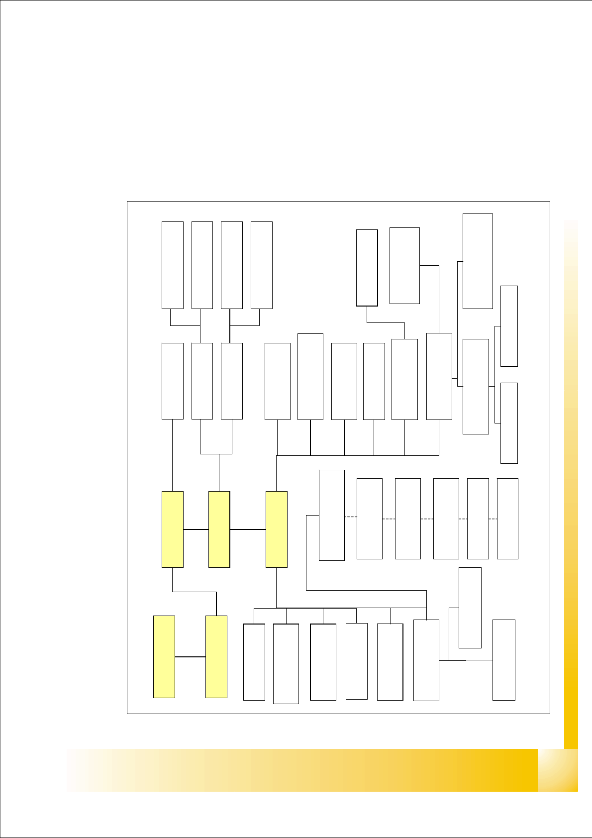
Abb. 3.1 - 1 Übersicht Kommunikation HF
Stations-Rechner
Maschinen-
Steuerung
SIPLACE Pro
COM-Platine
LP-Barcode
Tisch 1
Tisch 4 / MTC
Vision-Steuereinheit
Sektor 4
CAN E/A-Modul
Sektor 4
Transport
Steuerung
Axis Unit (BB2)
CAN E/A-Modul
Sektor 2
Vision-Steuereinheit
Sektor 2
Tisch 2 / MTC
Tisch 3
Kraftdaten
C&P-Kopf
CAN-Prozessorplatine
Magnetventil
LP Beleuchtung
Schrittmotor
Vakuum/Blasluft 3
Schrittmotor
DP-Station
Schrittmotor
Vakuum/Blasluft 1
Touch-Screen
ICOS 1
ICOS 2
LP-Kamera 1
BE-Kamera 1
LP-Kamera 2
Stationäre Kameras
Siplace LAN
V 24
HS3L
SMP-Bus
C
A
N
K
a
b
e
l
1
CAN Kabel 2
V 24
LP-Kamera
Beleuchtung
Twin-Head CAN
Prozessor Hauptplatine
Vakuumventile
CAN-Prozessor
Kopf-Schnittstelle
BE-Kamera
Beleuchtung
LP-Kamera
Beleuchtung
Twin-Head CAN
Prozessor Hauptplatine
CAN-Prozessor
Visionplatine
Dual LAN Unit