YG200_YG200L_Mainte_E.pdf - 第33页
2-1 2 Daily maintenance items 1 . C h e c k i n g t h e n o z z l e S o l d e r s t i c k i n g t o t h e n o z z l e t i p o r a c l o g g e d n o z z l e h o l e c a n c a u s e c o m p o n e n t p i c k u p e r r o r …

2-1
2
Daily maintenance items
1. Checking the nozzle
Solder sticking to the nozzle tip or a clogged nozzle hole can cause component pickup errors and
recognition errors. Poor nozzle spring action can also cause pickup and mounting errors. To prevent such
problems periodically inspect and clean each nozzle.
1.1 Check with software
n
How to check for a dirty nozzle (with the [Check Nozzle] button)
The term "dirty nozzle" as used here indicates shiny material such as solder adhering to the nozzle tip. This shiny portion
might be mistaken for a component and cause recognition errors. To check for this problem, press the [Check Nozzles]
button on the [Setup] screen while the nozzle tip picks up no components. The multi-vision camera finds the extent of
grime or dirt on the nozzle tip.
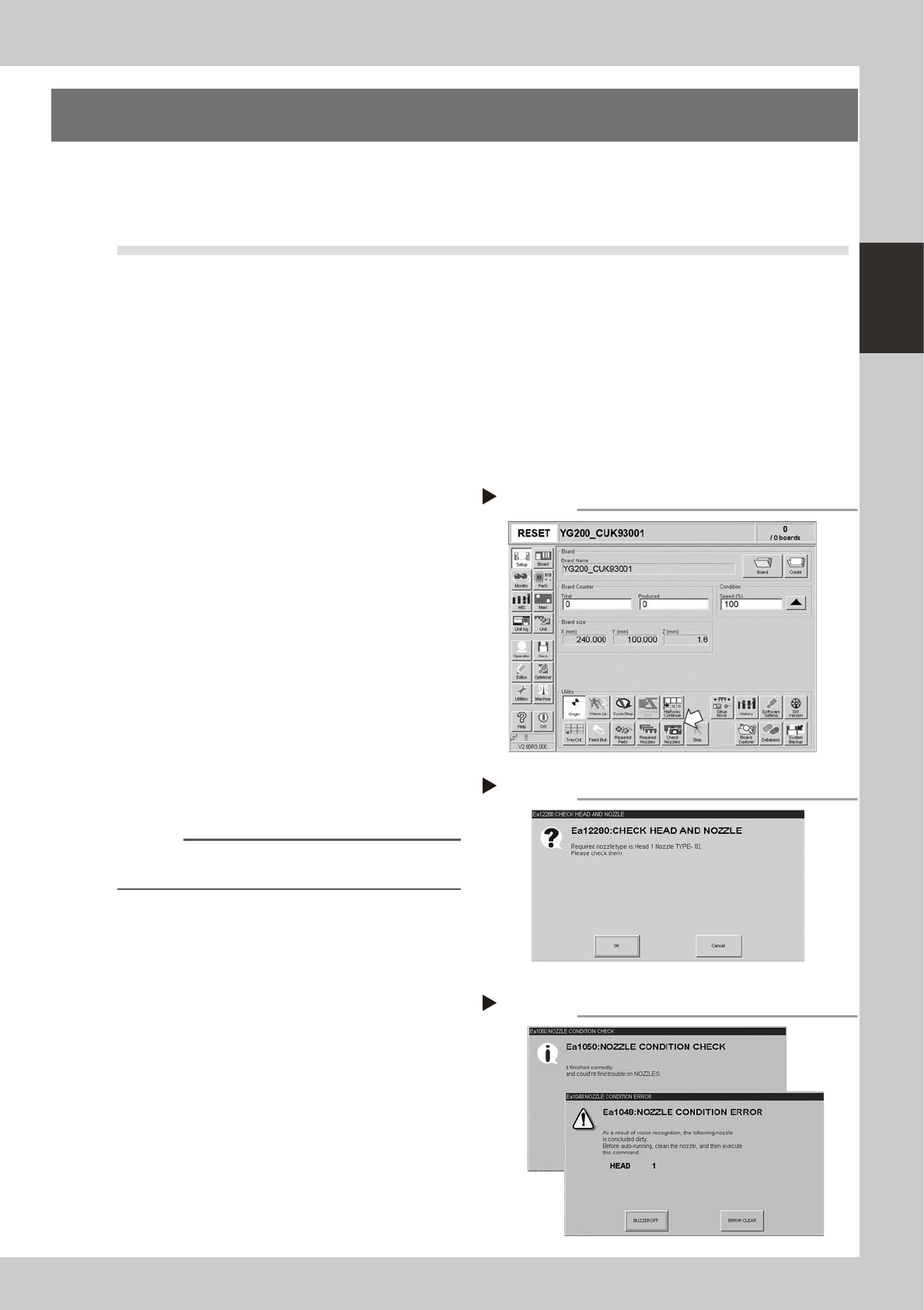
1
Move the head.
e
Press the emergency stop button and move
the head so the nozzle is at a position where
it can be easily replaced.
2
Press the [Check Nozzles] button as
follows.
1. Cancel emergency stop.
2. Open the [Setup] screen and press the
[Check Nozzles] button in "Utilities".
54200-F8-00
3
Change the nozzle.
Press the [OK] button for nozzle change
while following the message on the screen.
Nozzle change begins after pressing the last
[OK] button.
54201-F8-00
4
Check the message.
Clean the nozzle if the check shows it is dirty.
54202-F8-00
n
NOTE
The "Check Nozzles" function is usually set for "Type 202A
nozzles" before shipment.
[Check nozzles] button
Step 2
Message for checking head and nozzle
Step 3
Nozzle check results
Step 4
OK
NG
2-2
2
Daily maintenance items
n
How to check for clogged nozzles (on the [Unit] tab screen)
The term "clogged nozzle" used here indicates that material such as solder is adhering to the nozzle hole, causing a rise
in negative pressure even if there are no components present. This state might cause problems such as component
mounting errors. Check for clogged nozzles using the following procedure.
1
Attach the nozzle.
e
Press the emergency stop button and attach
Type 202A nozzles to all heads. When the
machine has a nozzle station, press the
[Nozzle Change] button to change the
nozzles.
54203-F8-00
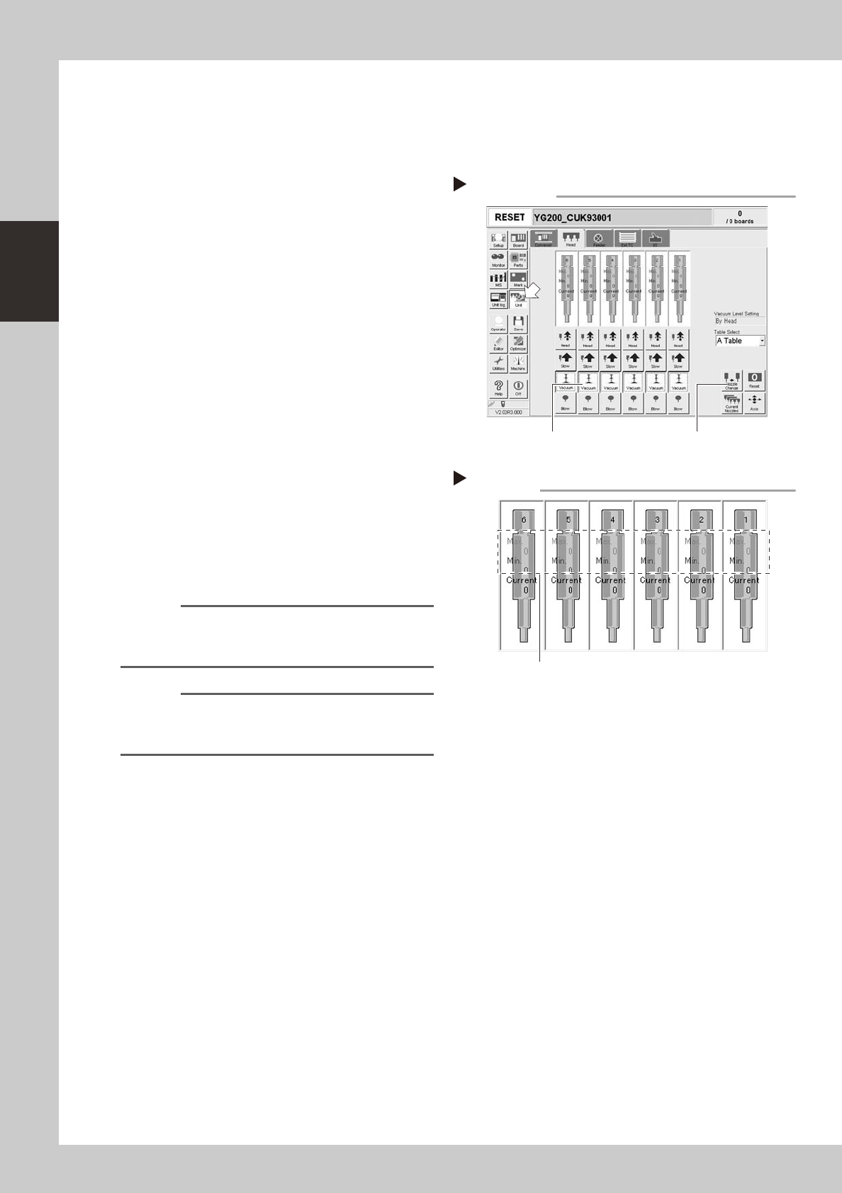
2
Reset the numerical figure.
Press the [Reset] button on the lower right of
the screen to reset the pickup level values.
3
Generate negative pressure.
Select [Unit] - [Head], and set the [Vacuum]
buttons for all heads to ON. When this value
starts rising, wait 5 to 10 seconds and set to
OFF.
4
Note the vacuum level.
When a figure appears in red on the head
screen, make a note of the "Max" reading. If
this figure is 110 or below then it is within
normal range. If this figure exceeds 110 then
the nozzle hole might be dirty so clean it.
54204-F8-00
n
NOTE
The above example is for Type 202A nozzles so the
figures shown will be different for other types of nozzles.
(Example: Type 201A => 180)
n
NOTE
If a correct figure cannot be obtained after cleaning
even after performing steps 1 to 4, then the interior of
the spline shaft might be dirty.
Negative pressure generation
Step 1 to 3
[Nozzle Change] button [Vacuum] button
Negative pressure check
Step 4
Take note of these figures.