YG200_YG200L_Mainte_E.pdf - 第42页
3-2 3 Periodic maintenance items 6 Lu b r i c a t e t h e s l i d e s e c t i o n . U s i n g a p r e c i s i o n s c r e w d r i v e r o r s i m i l a r t o o l w i t h a p o i n t e d t i p , a p p l y a s m a l l a m …
3-1
3
Periodic maintenance items
1. Weekly or biweekly inspection
Inspect and clean the nozzles weekly or biweekly as explained below.
1.1 Cleaning "Type A" nozzles
If solder adheres to a nozzle tip, the nozzle may be mistaken for a component or other problems may occur. If
nozzle spring-action is poor, pickup errors tend to occur frequently. To prevent these troubles, check the nozzle
condition and keep the nozzles clean.
e
1
Remove the nozzle from the head.
Always first press the emergency stop button
and then remove the nozzle from the head.
The machine must be in emergency stop to
ensure safety during work.
c
CAUTION
When the machine is equipped with a nozzle station,
make sure that the nozzles are returned to the nozzle
station.
2
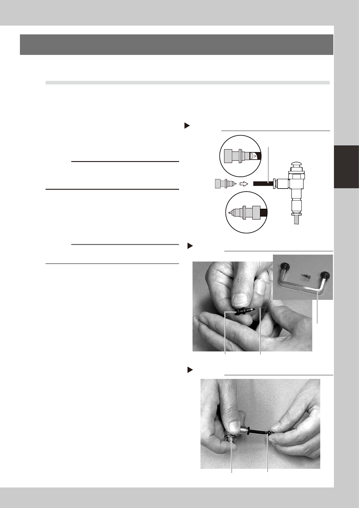
Blow air through the nozzle.
Using an air blow gun, blow air through the
nozzle from the nozzle tip and then from the
other end.
53300-F8-00
n
NOTE
If there are dust deposits in the nozzle, perform steps 3
and 4.
3
Clean the nozzle hole.
Pass the nozzle cleaning wire through the
nozzle hole and clean the nozzle hole. While
holding both ends of the wire with fingers as
shown or using a custom handle, gently
move the nozzle back and forth.
53301-F8-00
4
Blow air through the nozzle again.
After removing the cleaning wire, blow air
through the nozzle with the air blow gun, just
as in step 2.
53302-F8-00
5
Clean the slide section.
Apply IPA (isoprophyl alcohol) or ethanol to
the slide section. Push the nozzle tip several
times to repeat the buffing action (spring
action) to clean the slide section. After
cleaning, blow sufficient air to remove IPA or
ethanol.
Cleaning a nozzle
Step 3
Custom
handle
Nozzle
Nozzle cleaning wire
Air blow
Step 4
Nozzle
Air blow gun
Step 2
Air tube (black)
Air blow gun
(option)
Air tube (orange) connected to
air supply port
Air blow
Insert the
nozzle tip into
the air tube and
blow air.
Blow air from the
nozzle attachment
side.

3-2
3
Periodic maintenance items
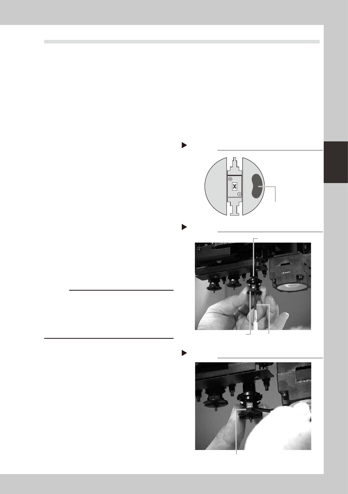
6
Lubricate the slide section.
Using a precision screwdriver or similar tool
with a pointed tip, apply a small amount of
turbine oil (just enough so that it sinks in) to
the slide section.
53303-F8-10
7
Check the buffing action (spring
action).
Push the nozzle tip several times to repeat
the buffing action and spread turbine oil.
Use a lint-free cleaning cloth to wipe away
excess oil from around the nozzle.
53304-F8-10
8
Remove excess oil remaining in the
nozzle.
Using an air blow gun, blow air for about 5
seconds from the nozzle tip, and for about 5
seconds from the nozzle attachment side.
Repeat this process a few times to remove
excess turbine oil remaining in the nozzle.
n
NOTE
A thin coat of oil is enough to lubricate the slide section.
9
Check that the oil was removed.
If needed, blow air through the nozzle again
while placing commercially-available oil
blotting paper over the opposite end of the
nozzle, and check for residual oil in the
nozzle.
n
NOTE
Performing step 8 is usually sufficient to remove oil
remaining in the nozzle. However, if oil still remains then
blow air through the nozzle once again.
53362-F8-00
0
Reinstall the nozzle.
Reinstall the nozzle back onto the head after
checking one more time that there is no oil
remaining there.
Lubricating the slide section
Step 6
Nozzle
Precision screwdriver
(with a small amount of turbine oil applied)
Checking the spring action
Step 7
Spring action at nozzle tip
Checking for residual oil
Step 9
Oil blotting paper
Oil will appear after blowing air (first
time) for about 5 seconds from the
nozzle tip.
Repeat the air blow for about 5
seconds each from the nozzle tip
and from the attachment side.
This task is finished when oil no
longer appears.
3-3
3
Periodic maintenance items
1.2 Cleaning Type F nozzles
1.2.1 Removing the FNC nozzle assembly
1
Select "Type 202 nozzle" for the
FNC heads.
On the [Unit]-[Head] tab screen, press the
[Nozzle Change] button and select
"Type-202" for the FNC heads (Heads 2, 4
and 6).
e
2
Press the emergency stop button.
The machine must be in emergency stop to
ensure safety during work.
3
Remove the black seal (KV8-
M71RH-00X) on the bottom of the
FNC head.
A black seal is affixed to the bottom of each
FNC head (Heads 2, 4, and 6) to cover the
screws that secure the stopper block.
Remove this black seal to loosen the screws
in the next step.
53305-F8-00
4
Remove the stopper block.
1. Use the Phillips screwdriver (No.1 or No.0)
to remove the two screws securing the
stopper block to the FNC head from the
bottom.
2. Remove the stopper block by sliding it
out.
53306-F8-00
53307-F8-00
c
CAUTION
• When loosening the stopper block screws, hold the
edge of the FNC assembly so it won't rotate.
The spline belt may otherwise slip on the gear teeth.
• The screwdriver bit size may slightly differ between
manufacturers. Use the screwdriver that matches the
recessed pattern on the screw head.
FNC head (when viewed from bottom)
Step 3
Black seal for nozzle index
Removing the stopper block
Step 4-1
Phillips screwdriver
Loose the screw while
holding this edge.
Stopper block
Step 4-2
Removing the stopper block
Slide out the stopper block by pushing it with a fingertip.