YG200_YG200L_Mainte_E.pdf - 第48页
3-8 3 Periodic maintenance items e C h e c k t h a t t h e o i l w a s r e m o v e d . I f n e e d e d , b l o w a i r t h r o u g h t h e n o z z l e a g a i n w h i l e p l a c i n g c o m m e r c i a l l y - a v a i l…
3-7
3
Periodic maintenance items
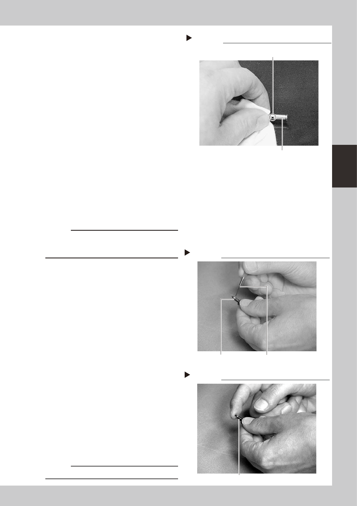
3. Clean the inside of the pinhole (air path)
in the middle of the bevel shaft by
passing the cleaning wire through it and
also wipe the shaft surface with a
cleaning cloth.
4. Clean other parts with cloth.
53315-F8-00
6
Blow air onto the cleaned parts.
Use the air blow gun (KU4-M8590-00X) to
blow air onto the cleaned parts.
7
Check that the nozzles were
cleaned.
Check the nozzles for clogging, nicks and
foreign matter
• If the nozzle tip is still clogged, reclean it
with alcohol or cleaning wire (KV8-
M8883-A0X).
• If the nozzle tip is nicked or foreign
matter cannot be removed, replace the
nozzle with a new one.
8
Reassemble the FNC nozzle
assembly.
Use the Phillips screwdriver to reassemble
the nozzles onto the nozzle block.
c
CAUTION
Use the screwdriver that matches the recessed pattern
on the nozzle mounting screw head. Do not forget to
insert the spring into the nozzle block.
9
Clean the slide section.
Apply IPA (isoprophyl alcohol) or ethanol to
the slide section. Push the nozzle tip several
times to repeat the buffing action (spring
action) to clean the slide section. After
cleaning, blow sufficient air to remove IPA or
ethanol.
0
Lubricate the slide section.
Using a precision screwdriver or similar tool
with a pointed tip, apply a small amount of
turbine oil (just enough so that it sinks in) to
the slide section.
53365-F8-00
q
Check the buffing action (spring
action).
Push the nozzle tip several times to repeat
the buffing action and spread turbine oil.
Use a lint-free cleaning cloth to wipe away
excess oil from around the nozzle.
53366-F8-00
w
Remove excess oil remaining in the
nozzle.
Using an air blow gun, blow air for about 5
seconds from the nozzle tip, and for about 5
seconds from the nozzle attachment side.
Repeat this process a few times to remove
excess turbine oil remaining in the nozzle.
n
NOTE
A thin coat of oil is enough to lubricate the slide section.
Cleaning the bevel gear shaft
Step 5-3
Bevel gear shaft
Clean the air path hole
in the middle of shaft.
Lubricating the slide section
Step 10
Nozzle Precision screwdriver
(with a small amount of turbine oil applied)
Checking the spring action
Step 11
Spring action at nozzle tip
3-8
3
Periodic maintenance items
e
Check that the oil was removed.
If needed, blow air through the nozzle again
while placing commercially-available oil
blotting paper over the opposite end of the
nozzle, and check for residual oil in the
nozzle.
n
NOTE
Performing step 12 is usually sufficient to remove oil
remaining in the nozzle. However, if oil still remains then
blow air through the nozzle once again.
53367-F8-00
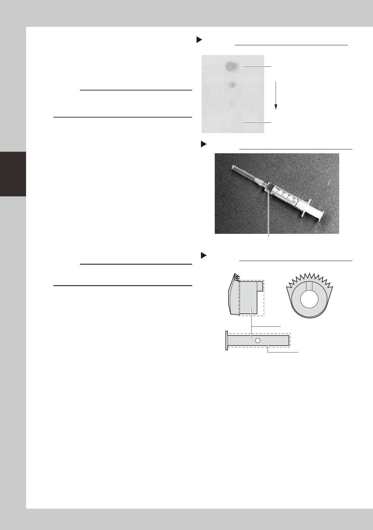
r
Lubricate the bevel gear, shaft and
nozzle sliding section.
Use the lubrication syringe (KV8-M8870-00X)
and turbine oil (VG32) to lubricate at the
following locations.
1. Apply one drop of oil at each of the
bevel gear inner sides and shaft, and
then spread it with your finger.
2. On spring-action nozzles, apply a small
amount of oil at the sliding section and
jog it back and forth several times by
pushing the nozzle tip. Remove the
excess oil and then blow with air.
53316-F8-10
53317-F8-10
c
CAUTION
Do not lubricate the bevel gear section, as foreign
matter may get caught in the gear.
t
Check the nozzle spring-action.
If the spring-action is still poor even after
cleaning, replace the nozzle with a new
one.
Lubrication syringe
Step 14
Turbine oil (VG32)
Lubrication points on bevel gear
Step 14-1
Shaft
Lubricate with one drop of oil.
Step 13
Checking for residual oil
Oil blotting paper
Oil will appear after blowing air (first
time) for about 5 seconds from the
nozzle tip.
Repeat the air blow for about 5
seconds each from the nozzle tip
and from the attachment side.
This task is finished when oil no
longer appears.
3-9
3
Periodic maintenance items
n
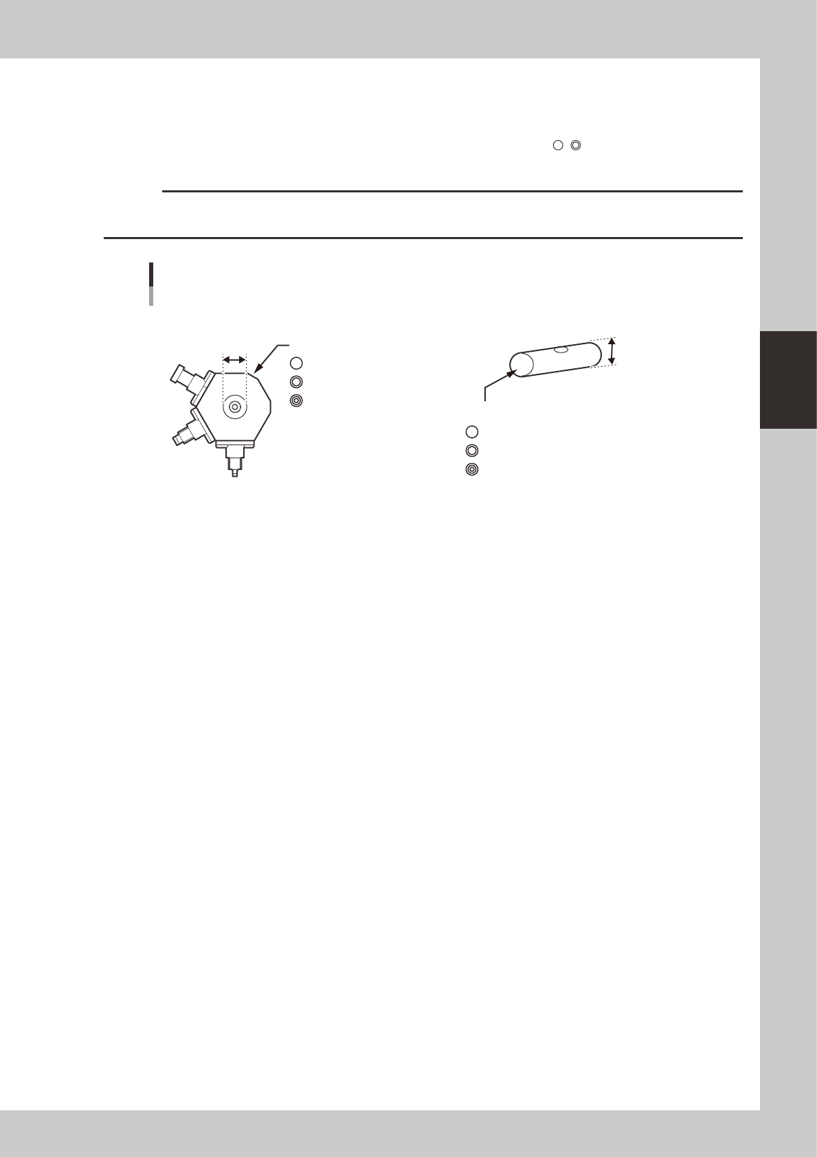
Precautions when replacing the bevel gear shaft (SHAFT_1)
Caution is required when replacing only the bevel gear shaft (SHAFT_1) during maintenance since a nozzle assembly and
SHAFT_1 must be used in the correct combination. There are 3 grades each of nozzle assemblies and SHAFT_1 depending
on the hole inner diameter and shaft outer diameter. They are identified by marks (
, , etc.) as shown below. Always
use the correct combination of a nozzle assembly and SHAFT_1 which have the same mark.
c
CAUTION
If the nozzle assembly and SHAFT_1 combination is incorrect, the nozzles may operate erroneously or vacuum leaks
may occur during component pickup.
4mm
4mm
4mm
NOZZLE ASSY (nozzle assembly)
There are 3 grades depending on the hole inner diameter.
ID mark
KV8-M71R1-10X mm
KV8-M71R1-20X 4mm
KV8-M71R1-30X 4mm
SHAFT_1
There are 3 grades depending on the outer diameter.
ID mark
Nozzle assembly and SHAFT_1 combination
53364-F8-00