YG200_YG200L_Mainte_E.pdf - 第50页
3-10 3 Periodic maintenance items 1 . 2 . 3 R e a s s e m b l i n g t h e F N C n o z z l e a s s e m b l y . 1 R e a s s e m b l e t h e F N C n o z z l e a s s e m b l y . 1 . O p e n t h e [ U n i t ] - [ H e a d ] t …
3-9
3
Periodic maintenance items
n
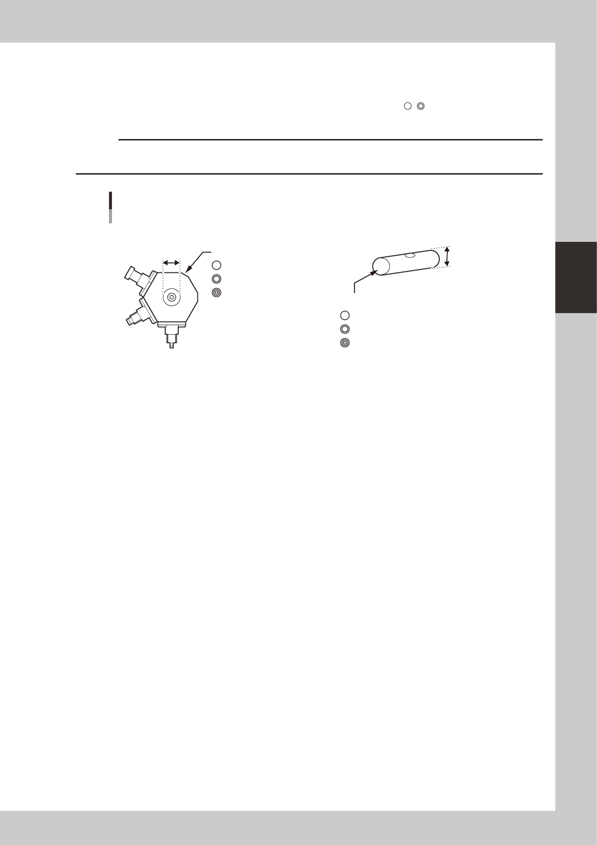
Precautions when replacing the bevel gear shaft (SHAFT_1)
Caution is required when replacing only the bevel gear shaft (SHAFT_1) during maintenance since a nozzle assembly and
SHAFT_1 must be used in the correct combination. There are 3 grades each of nozzle assemblies and SHAFT_1 depending
on the hole inner diameter and shaft outer diameter. They are identified by marks (
, , etc.) as shown below. Always
use the correct combination of a nozzle assembly and SHAFT_1 which have the same mark.
c
CAUTION
If the nozzle assembly and SHAFT_1 combination is incorrect, the nozzles may operate erroneously or vacuum leaks
may occur during component pickup.
4mm
4mm
4mm
NOZZLE ASSY (nozzle assembly)
There are 3 grades depending on the hole inner diameter.
ID mark
KV8-M71R1-10X mm
KV8-M71R1-20X 4mm
KV8-M71R1-30X 4mm
SHAFT_1
There are 3 grades depending on the outer diameter.
ID mark
Nozzle assembly and SHAFT_1 combination
53364-F8-00
3-10
3
Periodic maintenance items
1.2.3 Reassembling the FNC nozzle assembly.
1
Reassemble the FNC nozzle
assembly.
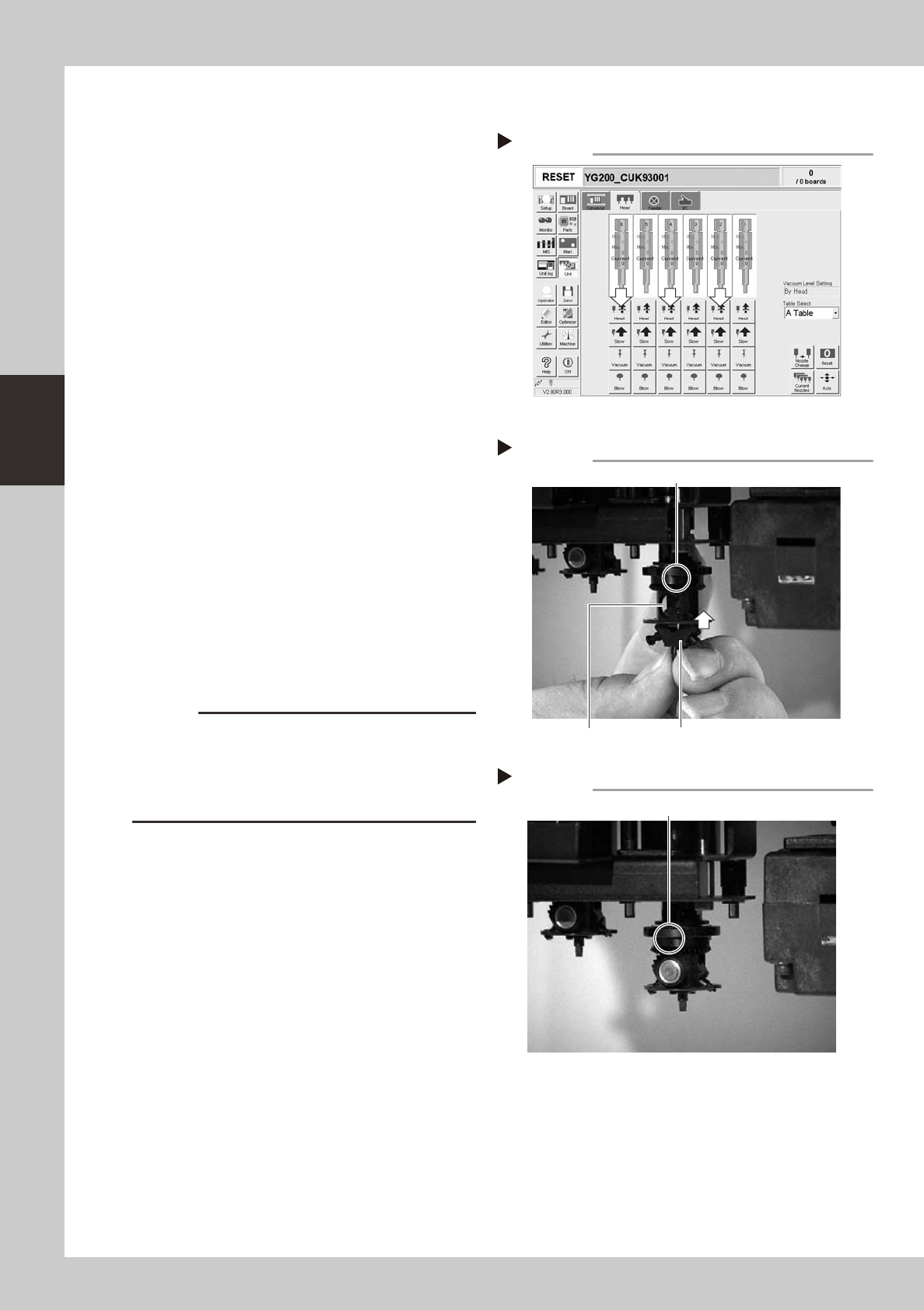
1. Open the [Unit]-[Head] tab screen and
press the [Head] button to lower the
head to which you are reassembling the
FNC assembly.
2. Rotate the R-axis belt so that the spline
shaft is positioned where the FNC nozzle
assembly can be easily reassembled,
and then set so that the inscribed mark
in the middle of the index holder faces
the front.
3. Hold the FNC nozzle assembly with the
cutout facing towards the front and Type
202F nozzle pointing downwards, and
insert it into the FNC head until the FNC
lock pin inside the index holder is slightly
raised.
54300-F8-00
53318-F8-00
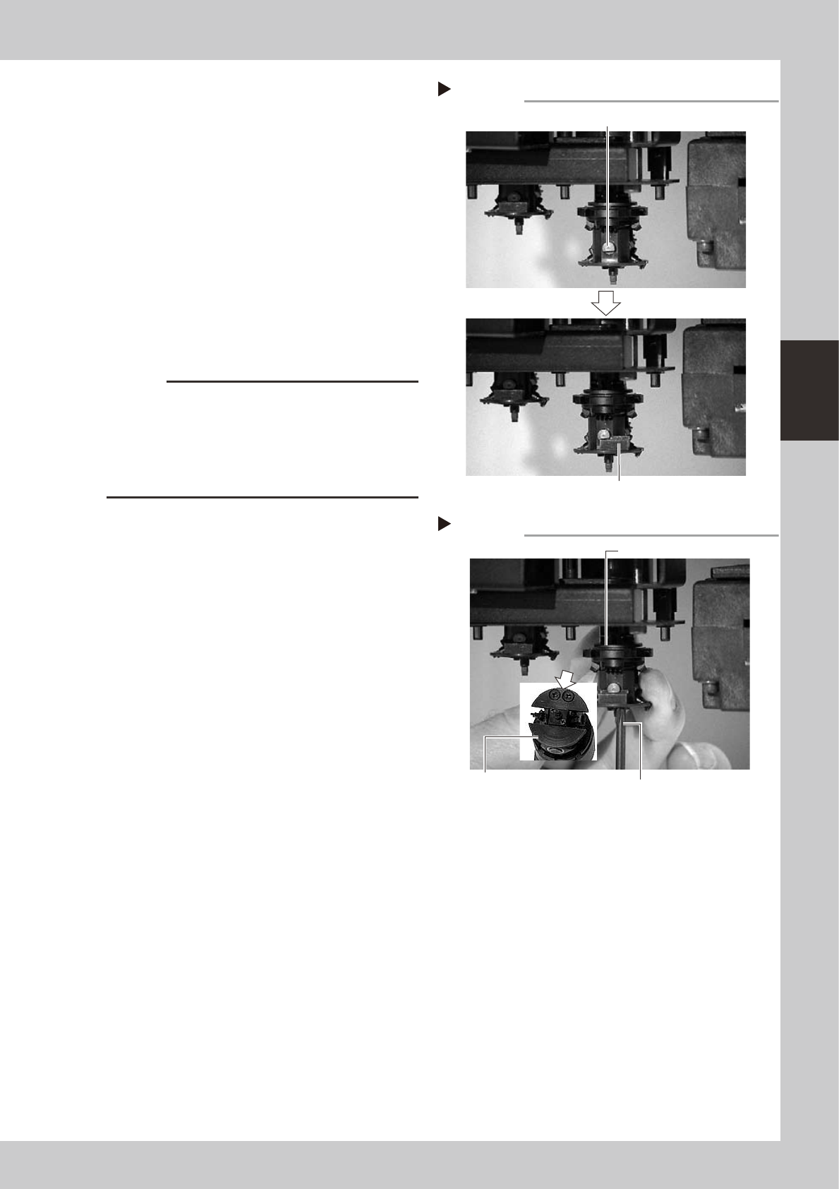
2
Insert the bevel gear and shaft.
While slightly pressing the FNC nozzle
assembly up, insert the bevel gear and shaft
into the center hole of the FNC nozzle
assembly from the front, and align the mark
on the bevel gear with the mark on the
index holder.
53319-F8-00
c
CAUTION
Reassemble the nozzle assembly, bevel gear and shaft
in their original combination for each FNC head, without
mixing them with parts for other heads. If this
combination is changed, the bevel gear may not rotate
smoothly or the pickup vacuum level may degrade.
[Head] up/down button
Step 1-1
2 4 6
Step 1-3
Inserting the FNC nozzle assembly
Type 202F nozzle should be pointed downwards.
This mark should face front.
Cut-out
Step 2
Aligning the marks
Align marks with each other.
3-11
3
Periodic maintenance items
3
Secure the FNC nozzle assembly.
1. Turn the R-axis belt so that the bevel gear
faces the opposite side.
2. Align the flat surface on the bevel gear
shaft horizontally and insert the stopper
block from the side.
3. Open the [Unit]-[Head] tab screen, and
press the [Head] button to raise the head
for which you have just reassembled the
FNC nozzle assembly.
4. Tighten the two screws with the Phillips
screwdriver (No.1 or No.0), to secure the
stopper block.
53320-F8-00
53321-F8-00
c
CAUTION
• When tightening the stopper block screws, hold the
edge of the FNC assembly so it won't rotate.
The spline belt might otherwise slip on the gear teeth.
• The screwdriver bit size may slightly differ between
manufacturers. Use the screwdriver that matches the
recessed pattern on the screw head.
5. Affix a new black seal (KV8-M71RH-00X)
to the heads of the stopper block screws.
When this black seal is not available,
check that the black coating on the
screw heads does not come off and no
light is reflected. If light is reflected from
the screw heads, replace the screws with
new ones or black out the reflecting
parts with a magic marker.
Step 3-2
Secure the FNC nozzle assembly
Position the flat face of shaft horizontally.
Insert the stopper block from the side.
Step 3-4
Securing the Stopper block
Stopper block
Tighten two screws
while holding this edge.
Phillips screwdriver