YG200_YG200L_Mainte_E.pdf - 第52页
3-12 3 Periodic maintenance items 4 C h e c k t h e m ov e m e n t a f t e r r e a s s e m b l y . 1 . A f t e r r e a s s e m b l i n g t h e F N C n o z z l e a s s e m b l y , p r e s s t h e [ H e a d ] b u t t o n o…
3-11
3
Periodic maintenance items
3
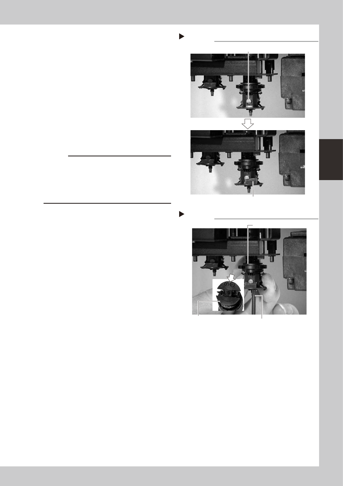
Secure the FNC nozzle assembly.
1. Turn the R-axis belt so that the bevel gear
faces the opposite side.
2. Align the flat surface on the bevel gear
shaft horizontally and insert the stopper
block from the side.
3. Open the [Unit]-[Head] tab screen, and
press the [Head] button to raise the head
for which you have just reassembled the
FNC nozzle assembly.
4. Tighten the two screws with the Phillips
screwdriver (No.1 or No.0), to secure the
stopper block.
53320-F8-00
53321-F8-00
c
CAUTION
• When tightening the stopper block screws, hold the
edge of the FNC assembly so it won't rotate.
The spline belt might otherwise slip on the gear teeth.
• The screwdriver bit size may slightly differ between
manufacturers. Use the screwdriver that matches the
recessed pattern on the screw head.
5. Affix a new black seal (KV8-M71RH-00X)
to the heads of the stopper block screws.
When this black seal is not available,
check that the black coating on the
screw heads does not come off and no
light is reflected. If light is reflected from
the screw heads, replace the screws with
new ones or black out the reflecting
parts with a magic marker.
Step 3-2
Secure the FNC nozzle assembly
Position the flat face of shaft horizontally.
Insert the stopper block from the side.
Step 3-4
Securing the Stopper block
Stopper block
Tighten two screws
while holding this edge.
Phillips screwdriver
3-12
3
Periodic maintenance items
4
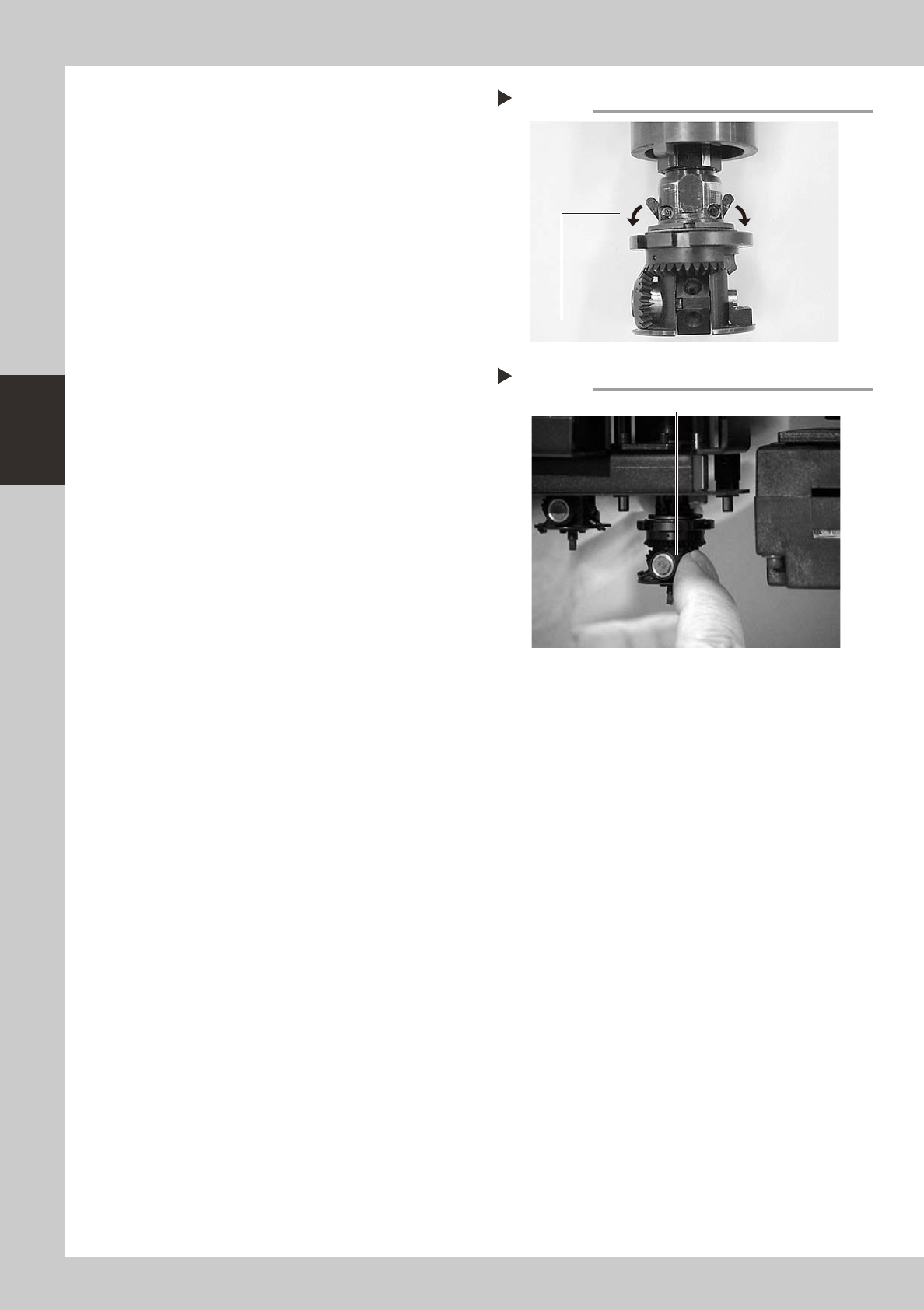
Check the movement after
reassembly.
1. After reassembling the FNC nozzle
assembly, press the [Head] button on the
[Unit]-[Head] tab screen to lower the
reassembled head.
2. Lower the FNC lock pin cam.
Lowering this cam releases the FNC lock
pin, allowing you to rotate the bevel
gear by hand.
3. With the cam still lowered, check that
rotating the larger bevel gear also
rotates the smaller bevel gear smoothly.
53322-F8-00
53323-F8-00
5
Check the nozzle change
movement.
On the [Unit]-[Head] tab screen, press the
[Nozzle Change] button to check that each
nozzle changes normally.
Releasing the FNC lock pin
Step 4-2
Lower the cam.
Step 4-3
Checking the bevel gear movement
Rotate the larger bevel gear to check movement.

3-13
3
Periodic maintenance items
1.3 Inspecting ball screws and linear guides of each axis
Inspect the ball screws and the linear guides on the X, Y and W axes. Check the following points.
Checkpoints
1. Any foreign matter adhering to the ball screws and linear guides?
Check if any fallen chips have adhered to the X and Y axis ball screws and/or X, Y and W axis linear guides.
2. Do the ball screws and linear guides have the correct amount of grease?
Check if grease has flowed off or splattered in the air failing to adhere. Also check if grease has discolored or hardened.
3. Any abnormal sounds from the ball screws?
Press the emergency stop button. Then check for any abnormal sounds while pressing the head assembly or conveyor
table by hand along the X-axis or Y-axis back and forth.
Countermeasures
1. Ball screws and linear guides may be damaged when chips and other material bite into them. If chips are adhering,
wipe them off along with the grease or remove with tweezers, etc.
2. Apply grease while referring to "2.2 Cleaning and greasing the X, Y, YT and W axis ball screws" and "2.3 Cleaning and
greasing the X, Y, YT and W axis linear guide rails" explained in chapter 3.
3. Consult your YAMAHA dealer when abnormal sounds occur even after trying the countermeasures in the above steps 1
and 2.