YG200_YG200L_Mainte_E.pdf - 第68页
3-28 3 Periodic maintenance items 6 A f t e r a s s e m b l y , c h e c k t h e v a c u u m l e v e l s . 1 . C h a n g e t h e n o z z l e o f e a c h F N C h e a d t o T y p e 2 0 3 F , w h i l e l e a v e n o z z l e …
3-27
3
Periodic maintenance items
3.2.3 Attaching the nozzle, lubricating and checking negative pressure
After cleaning the spline shafts, reattach the nozzles and lubricate them. Also check the negative pressure
(vacuum level) as described below.
1
Install the FNC nozzle assemblies.
Reassemble the FNC nozzle assemblies by
referring to section 1.2.3, "Reassembling the
FNC nozzle assembly" in this chapter.
2
Lubricate each part.
Lubricating oil has been cleaned away by
IPA cleaning, so lubricate the following
parts. Prepare the oil syringe applicator
(KV8-M8870-00X) filled with turbine oil
(VG32).
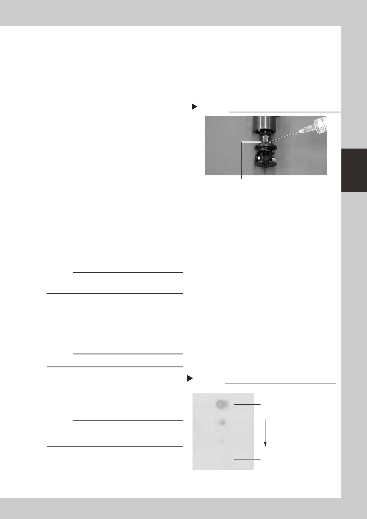
1. On standard heads, apply one drop of
oil into the elongated holes at the joint
between the nozzle holder and the spline
shaft. (2 holes on each head) After
applying the oil, move the nozzle holder
up and down several times.
2. On FNC heads, pull down the FNC index
holder, and you will see two small cams
on the FNC spline shaft. Apply one drop
of oil onto each cam and then move the
cams up and down several times.
3. Apply one drop of oil to the inner side of
the FNC bevel gear and shaft, and then
spread out the oil with your finger.
53345-F8-00
c
CAUTION
Do not lubricate the bevel gear section, as oil attracts
dust or debris which might get caught in the gear.
3
Remove excess oil.
Using the air blow gun, blow air for about 5
seconds from the nozzle tip, and for about 5
seconds from the nozzle attachment side.
Repeat this process a few times to remove
excess turbine oil remaining in the nozzle.
n
NOTE
A thin coat of oil is enough to lubricate the slide section.
4
Check that the oil was removed.
If needed, blow air through the nozzle again
while using commercially-available oil
blotting paper, and check for residual oil in
the nozzle.
n
NOTE
Performing step 3 is usually sufficient to remove oil
remaining in the nozzle. However, if oil still remains then
blow air through the nozzle once again.
53371-F8-00
5
Reattach the nozzles.
Attach the nozzles back to the head after
checking one more time that there is no oil
remaining there.
Lubrication point
Step 2
FNC cam
Step 4
Checking for residual oil
Oil blotting paper
Oil will appear after blowing air (first
time) for about 5 seconds from the
nozzle tip.
Repeat the air blow for about 5
seconds each from the nozzle tip
and from the attachment side.
This task is finished when oil no
longer appears.
3-28
3
Periodic maintenance items
6
After assembly, check the vacuum
levels.
1. Change the nozzle of each FNC head to
Type 203F, while leave nozzles detached
from the standard heads.
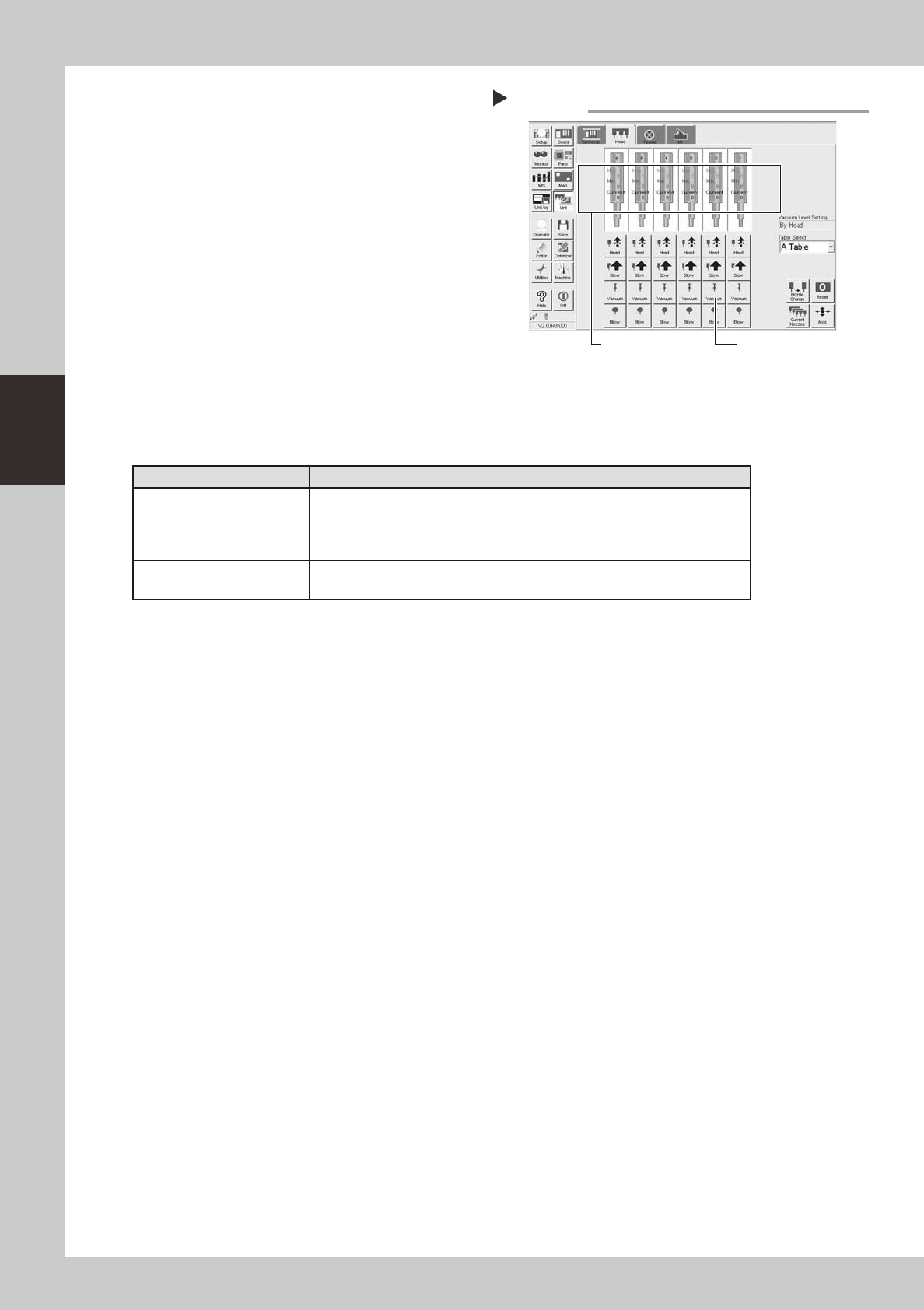
2. Open the [Unit]-[Head] tab screen and
press the [Vacuum] button to generate a
negative pressure. Read the "Max" values
shown in red on the screen and
determine whether the vacuum levels
are appropriate by referring to the table
below.
54302-
F
8-00
7
Reattach the nozzles.
Attach the nozzles by hand back to the
standard heads.
n
Vacuum level in spline shaft air path
Nozzle
Typical criteria
FNC head with Type 203F
nozzle
If the "Max" value is less than 100 while the nozzle is open, the vacuum level is
normal.
If the "Max" value is more than 170 while the nozzle is sealed, the vacuum level
is normal.
Standard head with no nozzle
If the "Max" value is less than 80 while open, the vacuum level is normal.
If the "Max" value is more than 180 while sealed, the vacuum level is normal.
* The vacuum level in in the spline shaft air path might sometimes differ slightly depending on the air source and
operating conditions. Use the above criteria values for reference during maintenance.
Checking the negative pressures
Step 6
[Vacuum] button
Read "Max. values".
3-29
3
Periodic maintenance items
3.3 FNC lock pin
Inside the spline shaft of each FNC head ("F" type heads 2, 4 and 6), a lock pin (or locate pin) is used to lock
the rotation of the FNC nozzle assembly when the selected nozzle points downwards. If dust or grime adheres
to this lock pin, the R-axis spline belt might skip teeth or component pick-and-place errors might occur.
Although depending on the operation time, clean the FNC lock pin once a year. Follow the procedure below to
clean the FNC lock pin.
3.3.1 Removing FNC lock pin
1
Select "Type 202F nozzle" for the
FNC heads.
On the [Unit]-[Head] tab screen, press the
[Nozzle Change] button and select
"Type-202" for the FNC heads (Heads 2, 4
and 6).
2
Press the emergency stop button.
e
The machine must be in emergency stop for
safe maintenance work.
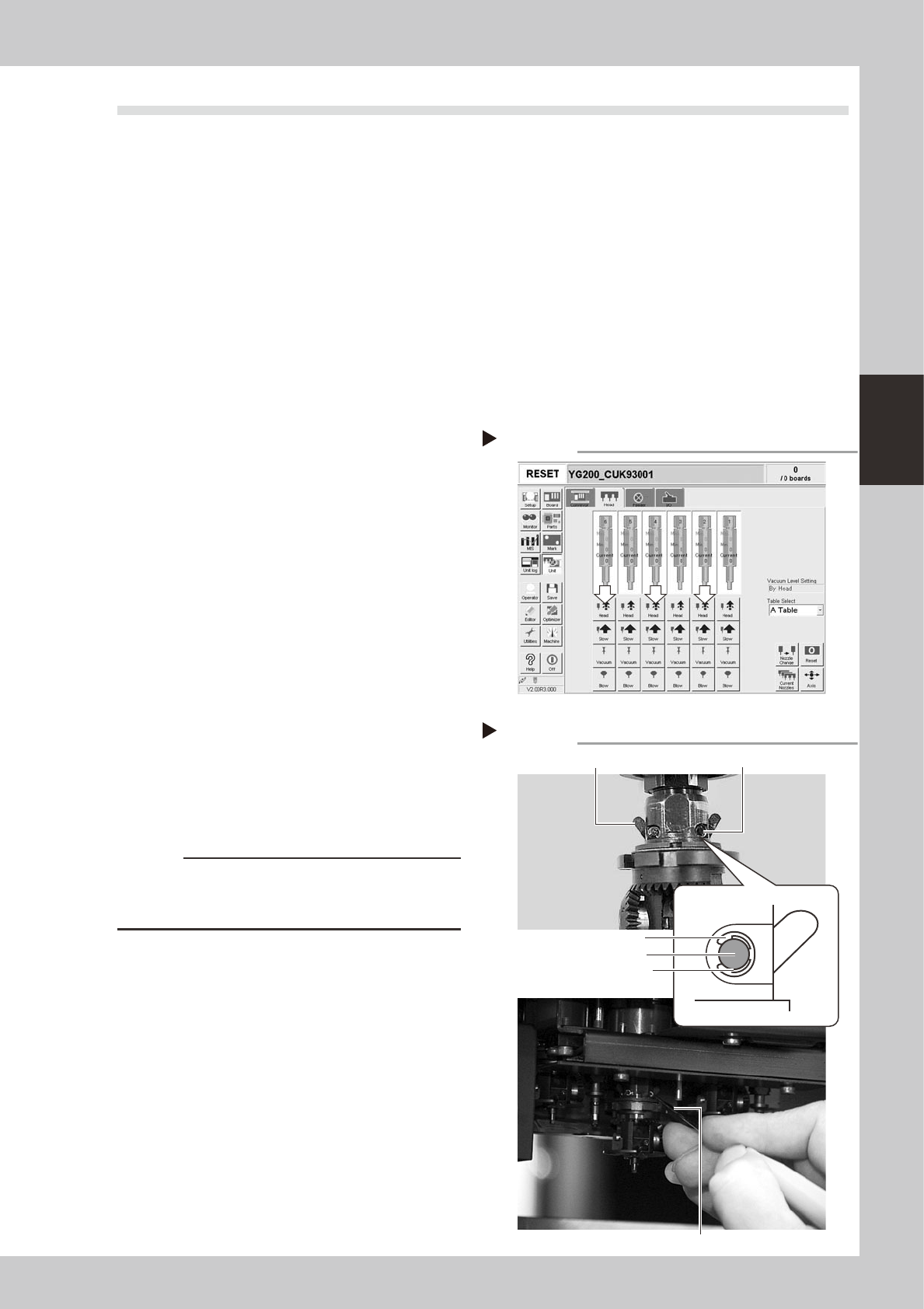
3
Lower the spline shaft of the FNC
head.
On the [Unit]-[Head] tab screen, press the
[Head] button to lower the head. Two small
cams located just above the bevel gear
appear. (These cams move as the FNC lock
pin inside the spline shaft moves.)
54301-F8-00
4
Remove the E-rings that fasten the
cam pins.
1. Rotate the R-axis belt so that the spline
shaft is positioned where the E-ring can
be easily removed.
2. Insert the E-ring remover into the gap
between the E-ring and the cam pin,
and pry it to remove the E-ring. (There
are two E-rings for each FNC head.)
53346-F8-00
c
CAUTION
Use caution when removing the E-ring so that it won't fly
out. The E-ring once removed cannot be reused.
Always use a new E-ring for reassembly.
[Head] up/down button
Step 3
246
Removing the E-ring
Step 4
Cam
E-ring
E-ring remover
Insert the E-ring remover between
E-ring and pin to remove E-ring.
Cam Cam pin