FUJI 24 HEAD Replacing ALL syringe_IPS.pdf - 第38页
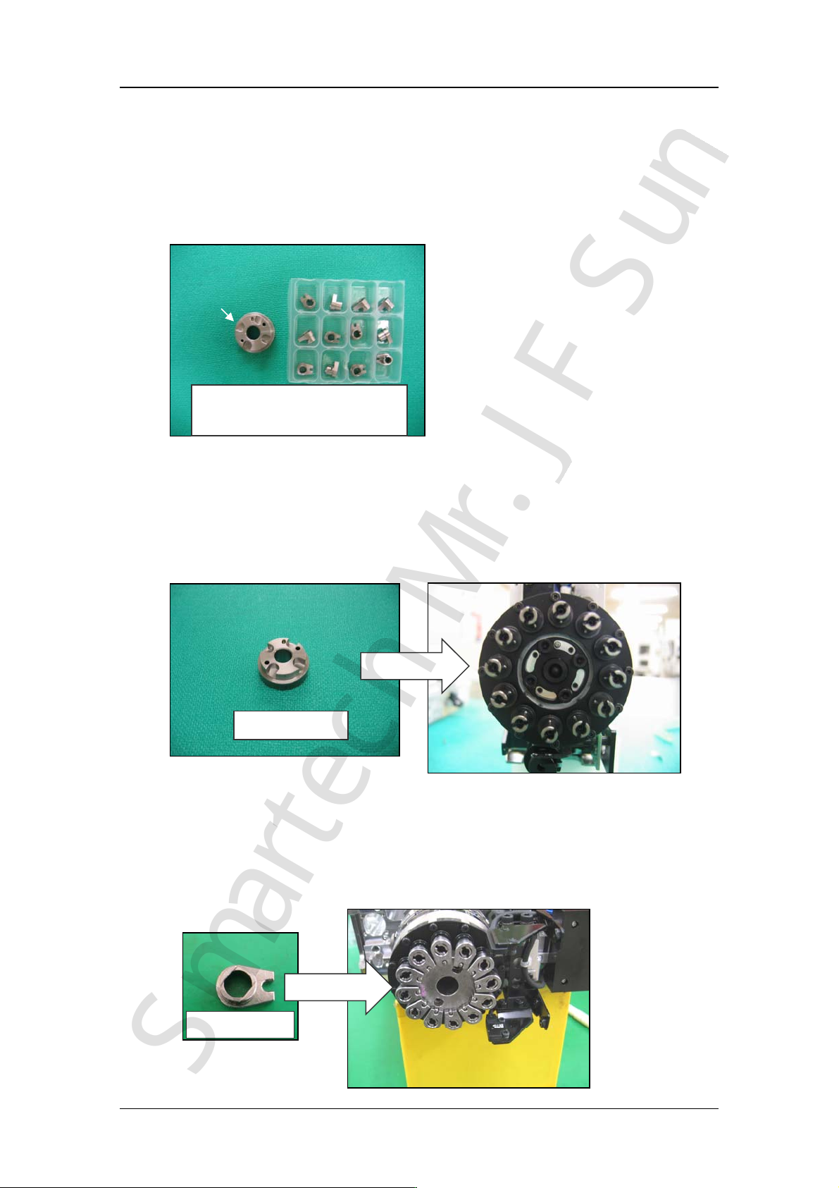
Edition 2.0 NXT/NXT2 Repair Training T ext H12HS(Q) Hea d FK-9F98-61-0E 7-10 FUJI MACHINE MFG . CO., L TD. 3 ) As shown in the following photo, align the cu tout section of the jigs attached to the syringes with the pins…
Edition 2.0 NXT/NXT2 Repair Training Text
H12HS(Q) Hea
d
FK-9F98-61-0E 7-9 FUJI MACHINE MFG. CO., LTD.
18. Attach the syringe gear to the syringe. Follow the procedure below when using the
H12HSθ-axis phase alignment jig (AA6LH0*).
Note: The PM6637* component of the H12HS θ-axis phase alignment jig (AA6LHO*) is
the same as that used for the H12Sθ-axis phase alignment jig
.
However, the
jig PM07RA is only for the H12S head.
1) Attach the H12HSθ-axis phase alignment jig(PM6637*) to the rotary holder.
Note:
The H12HSθ-axis phase alignment jig
(
PM6637*
)
is also used as the H12S
head θ-axis phase alignment jig.
2) Attach the H12HSθ-axis phase alignment jig (PM07RA*)to all the syringes.
Caution: The jig (PM07RA*
)
should only be used on the H12HS head. It is not for use
on the H12S head.
H12HSθ-axis phase
alignment jig (AA6LH0*)
PM6637*
PM07RA*
PM6637*
PM07RA*
CONFIDENTIAL
SmartechMr.J FSun
Edition 2.0 NXT/NXT2 Repair Training Text
H12HS(Q) Hea
d
FK-9F98-61-0E 7-10 FUJI MACHINE MFG. CO., LTD.
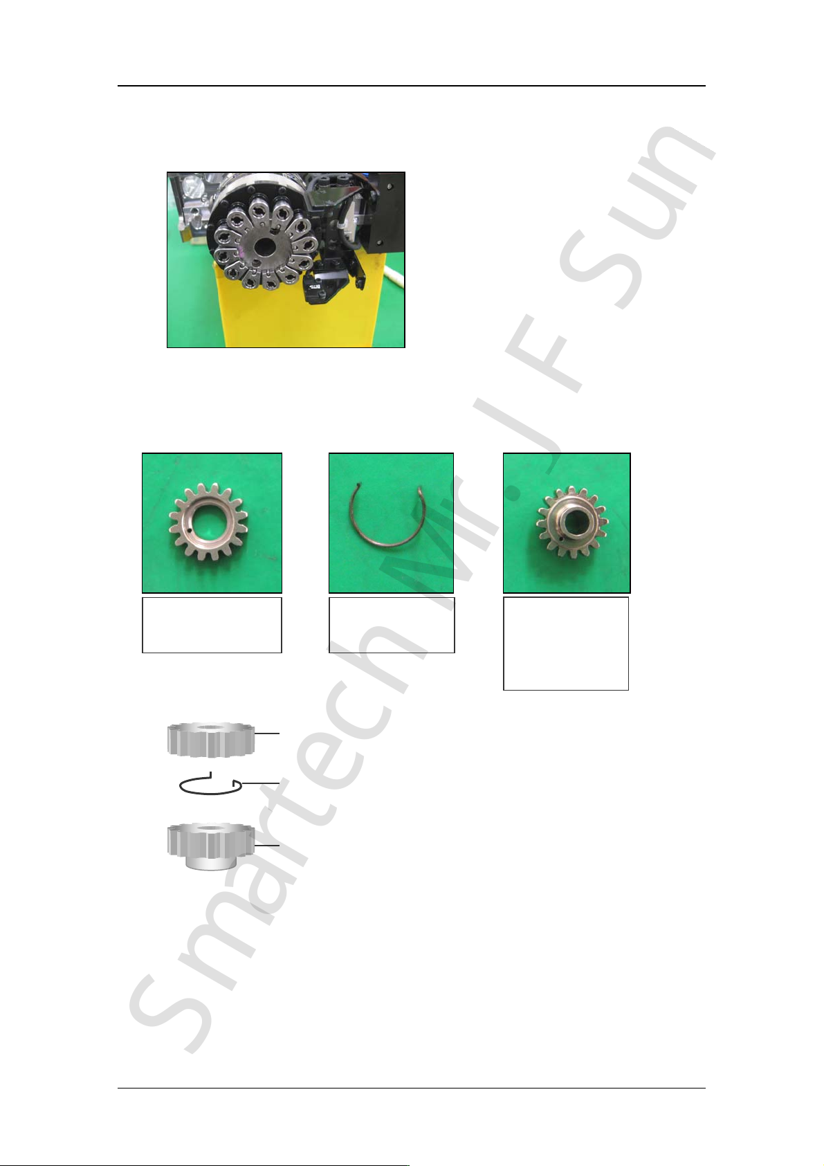
3) As shown in the following photo, align the cutout section of the jigs attached to the
syringes with the pins on the other jig. Under these conditions the phases of the
syringe, gear and rotary holder are all aligned.
19. When attaching a new syringe gear, the syringe to which the gear should be attached
differs depending on the holder position. Refer to the table on the following page to
prepare an appropriate gear.
Upper gear
(PM04MK*)
Lower gear
(PM4MH*)
(PM053S*)
(PM053T*)
Spring
(PZ3439*)
Upper gear
Spring
Lower gear
CONFIDENTIAL
SmartechMr.J FSun
Edition 2.0 NXT/NXT2 Repair Training Text
H12HS(Q) Hea
d
FK-9F98-61-0E 7-11 FUJI MACHINE MFG. CO., LTD.
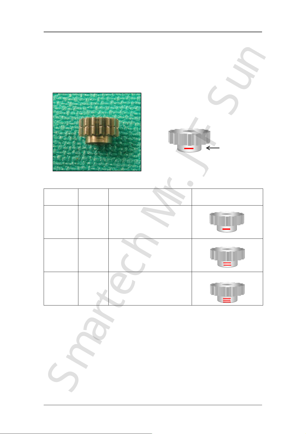
Caution! There are 3 types of H12HS syringe gears. As shown in the table below,
each gear type can only be attached to specific holders.
The gears can be
differentiated by the number of engraved lines (1, 2 or 3).
Caution! Initial models of the H12HS head have a number (1, 2, or 3) stamped on the
top surface of the lower gear instead of engraved lines. The number cannot
be checked when the upper and lower gear have been assembled together.
Part Name Part No. Notes
Gear 1 PM4MH* Attach to holders A, D, G, J
Gear 2 PM053S* Attach to holders B, E, H, K
Gear 3 PM053T* Attach to holders C, F, I, L
Example: Gear 1(PM4MH*) (For holders A, D, G, J)
Engraved line
CONFIDENTIAL
SmartechMr.J FSun