Specification SIPLACE CS-Speed - 第16页
14 Description The component chan geover tables can be s et up and che cked at an external SIPLACE set-up station quickl y and witho ut mac hine idle time. The costs for production in- volving a wide variety of compo- ne…
13
Description
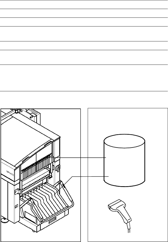
The bar code scanner enables a
quick and reliable check of com-
ponent set-up and refill. The bar
codes of the tracks and the loaded
components assigned to the
tracks (bar code labels on tapes,
Bulk Cases, etc.) are read in with
a hand scanner. An audible and
optical signal acknowledges a suc-
cessful reading operation. If the
label is damaged the bar code
can be entered at the keyboard.
The allocation of the components
to their respective track is de-
scribed in the set-up data. An error
message is displayed if the data
received from the bar code scan-
ner does not conform to the set-up
data.
If the set-up check is switched
on, it becomes a mandatory step
in the set-up process. If it is
switched off the set-up check
is optional.
Component Supply:
Component Bar Code Scanner for Set-Up and Refill Check
(Option)
Technical Data
Connection Station computer
Data input Bar code scanner or keyboard
Number of characters Max. 40
Restrictions Bar codes beginning with number 1 or 2
and with less than 5 characters
Number of bar codes Max. 6 per component
Number of filters
to extract relevant data Max. 1 per bar code
Preset code types Code 39 (standard or full ASCII),
Code 2 from 5 interleaved and normal,
Code 128, UPC/EAN/JAN codes
(more on request)
Scanner
Component
Control
Set-Up File
Track Bar Code
Scanner
Component
Bar Code
The scanner checks the corresponding track and the components
14
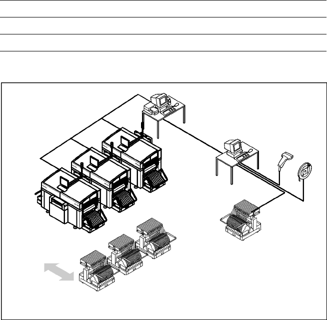
Description
The component changeover tables
can be set up and checked at an
external SIPLACE set-up station
quickly and without machine idle
time. The costs for production in-
volving a wide variety of compo-
nents are greatly reduced. During
the bar code check outside the
machine, 10 minutes of machine
standstill are eliminated per set-up
change. All current data from up to
4 lines are accessible over a link to
the line computer via a Local Area
Network (LAN).
In the case of the SIPLACE CS a
component changeover table is
part of the standard equipment.
Additional changeover tables are
required for optimal use
of the set-up station.
Component Supply:
SIPLACE External Set-Up Station (Option)
Technical Data
Operating system Windows XP
Set-up check Per bar code scanner
Component table change Time expanded: 2 min / table side
Example for SIPLACE Set-Up Station
Line
LAN
SIPLACE C Pro
PC for External set-up
LAN Scanner
Serial Interface
Tape Reel
with
Bar Code
Mobile
Changeover
Table
Mobile
Changeover
Tables
15
Description
The SIPLACE CS has a number of
vision modules and a central vision
system to evaluate the recorded
image data ensuring high place-
ment accuracy.
At the machine´s X-gantry the PCB
vision module is mounted. It is
used to find the PCBs´ positioning-
offsets within the conveyor sys-
tem.
This vision module is also required
to measure the machine origin
and/or the feeder positions on one
side of the table. It consists of a
single CCD camera with integrated
lighting and optics.
The offsets in the position of the
PCBs are determined with the
help of at least two but generally
three reference fiducial marks on
the PCB. When the PCB arrives at
the placement area the positioning
system with its PCB vision module
moves to the programmed mark
position.
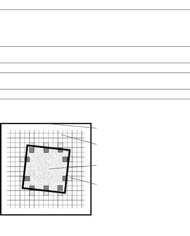
Using the Geometrical Alignment
allows to choose predefined marks
from a menu (e.g. cross, circle,
square). The size of the mark is
programmed at the Station Com-
puter. From this time on form and
size of the mark is defined and
known.
With this data the PCB vision
module is able to search and rec-
ognize the mark at the predefined
position on the PCB or ceramic
substrate without further assis-
tance. For this reason it places
several small evaluation windows
at the assumed border of the
mark. Within these evaluation
windows the vision system looks
for contrast transitions between
bright and dark. After finding such
contrasts the actual position of the
mark can be assigned by compari-
sion with the predefined – and
thus known – form and size.
Evaluation operations calculate
possible PCB offsets against given
values of X-, Y- and Theta-axis.
Saving the mark by teaching is not
necessary any more.
Additional functions of the PCB
vision module are recognition of
the position of the feeders and
ceramic substrate (optional) and
recording of the machine data in-
cluding mapping.
In addition, the bad board recogni-
tion unit handles “ink spots” with
the aid of the PCB vision module.
Vision Sensor Technology:
PCB Vision Module
Technical Data
Reference marks
Local marks
Library memory
Recognition of bad boards
up to 3 (subpanels and multiple panels)
up to 2 per component
(may be of different type)
up to 255 types of reference marks
per subpanel
Image analysis Correlation principle (geometric
alignment) based on gray-scale values
Lighting method Front lighting
Recognition time fiducial/
bad board marks
0.4 s
a
Camera’s field of view 5.7 x 5.7 mm
a) Software 502.xx required.
Geometrical Alignment
Camera’s field of view
Pixel
Ink spot, e.g. square
Evaluation window