Specification SIPLACE CS-Speed - 第21页
19 Description Despite the highl y stable machine frame, slight distortions of the gentry axes cannot al ways be avoided. With the aid of the mapping process the hig h place- ment accuracy of the ma chine is preserved th…

18
Description
The standard component vision
module is directly integrated into
the Collect & Place Head. While
the component is cycling into the
next station of the Collect & Place
Head, the recorded image is eva-
luated by the central vision sys-
tem. The component rotation is
then corrected by the appropriate
angle based on the position off-
sets determined with vision in-
spection.
Vision Sensor Technology:
Standard Component Vision Modules for the 6-Nozzle
Collect & Place Head
Standard Component Vision Module for the 6-Nozzle C & P Head
Component size
minimum
maximum
0.6 x 0.3 mm
2
(0201)
18.7 x 18.7 mm
2
Component range See table on page 6
Camera’s field of view 24 x 24 mm
2
Illumination Front light
(3 freely programmable planes)
Pixel size 50 µm
19
Description
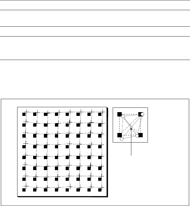
Despite the highly stable machine
frame, slight distortions of the
gentry axes cannot always be
avoided. With the aid of the
mapping process the high place-
ment accuracy of the machine is
preserved throughout its entire
service life.
With this calibrating procedure,
which can be conducted quickly
and easily, the PCB camera recog-
nizes the fiducials on a mapping
calibration plate placed in its oper-
ating area. Any distortions are re-
vealed by comparing the nominal
grid on the glass plate with the
actual grid “drawn” by placement
head. These distortions are taken
into account during all further
positioning of X-/Y-axes and
thus compensated for.
Machine Criteria:
Mapping (Option)
Technical Data
Dimensions of the mapping test plate 520 x 460 mm
2
Number of measurement points 13 x 11 (standard resolution)
26 x 21 (high resolution)
Ambient temperature during calibration + 20° ± 3°C
Components of the option Test plate (special glass)
Calculation data (disk)
Case for secure storage
Nominal Grid of Mapping Plate and Actual Grid with
Deviations Due to Gantry
Corrected
Position
20
Description
Line Programming Sy
Line Programming SyLine Programming Sy
Line Programming Sys
ss
stem
temtem
tem
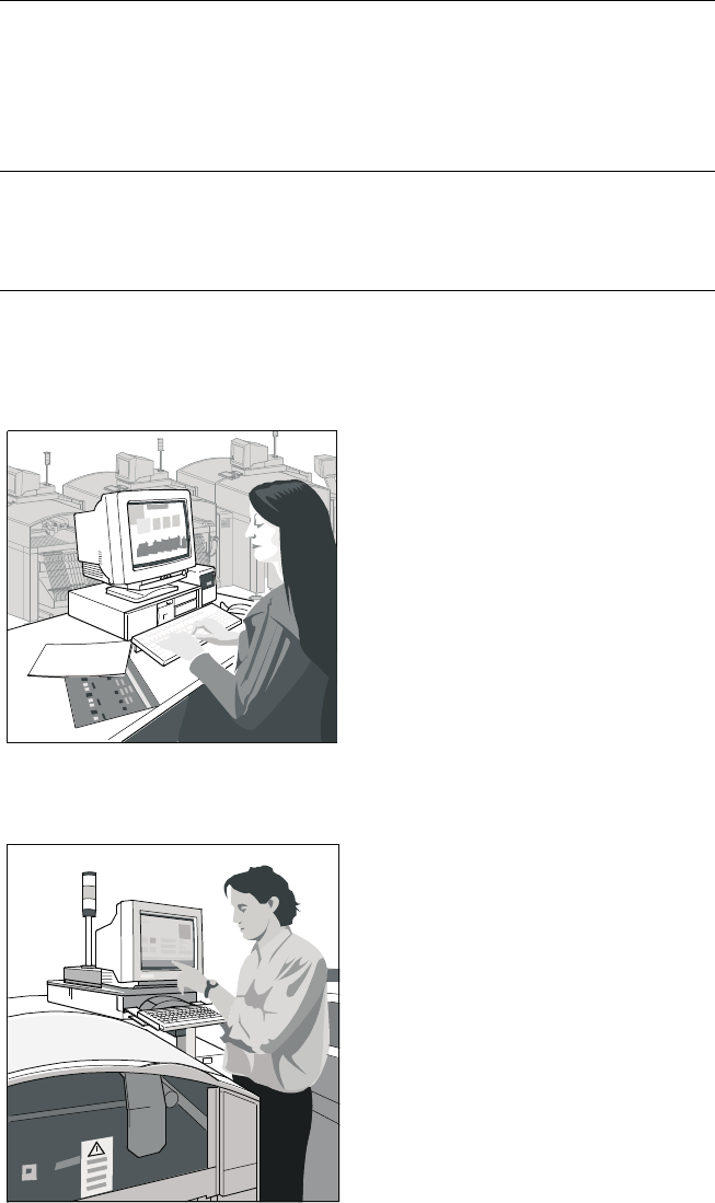
The programming System
SIPLACE C Pro, which runs on
standard PC using Windows XP
operating system, optimizes and
controls complete SIPLACE
placement lines. Consequently
secondary times are reduced and
maximum productivity is guaran-
teed. A graphical user interface
eliminates operating errors.
Station Computer
Station ComputerStation Computer
Station Computer
The station computer in conjunc-
tion with the machine controller
with its realtime capability per-
forms the following jobs: digital
control of the machine gantry
systems; control of PCB input
and output and of PCB transport;
monitoring functions, handling of
malfunctions and output of error
messages (including Help system);
ensuring the optimal quality of the
placement process.
SIPLACE Software Architecture:
Line Programming System
Station Computer
Line Programming System
Station Computer
Functions
Line Programming System for
Software
Data Preparation – Virtual Product Build
Optimization
Line control
Line monitoring
Data management
SIPLACE C Pro (Windows XP)
Station Computer for
Software
Machine control
Machine monitoring
Machine operation
SW 1.01