Specification SIPLACE CS-Speed - 第22页
20 Description Line Prog ramming Sy Line Prog ramming Sy Line Prog ramming Sy Line Prog ramming Sys s s st e m tem tem tem The programming S ystem SIPLACE C Pro, which runs on standard PC using W indows XP operating syst…
19
Description
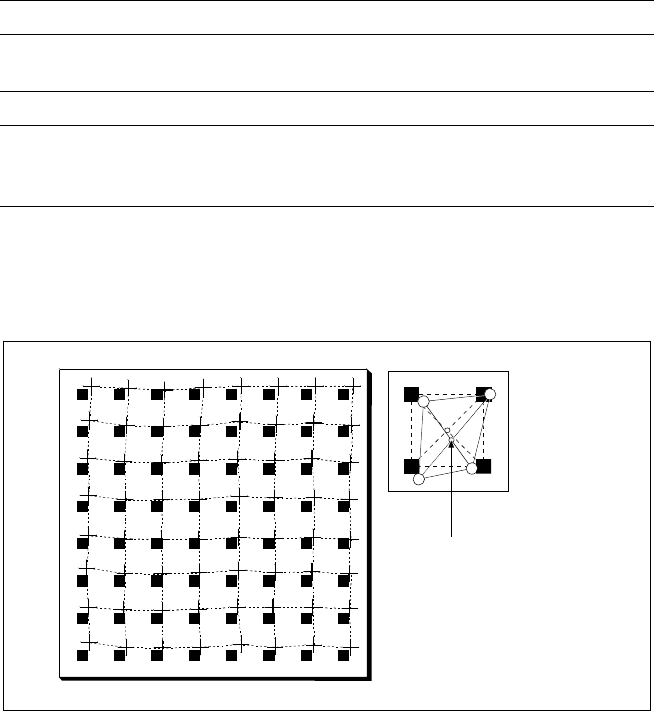
Despite the highly stable machine
frame, slight distortions of the
gentry axes cannot always be
avoided. With the aid of the
mapping process the high place-
ment accuracy of the machine is
preserved throughout its entire
service life.
With this calibrating procedure,
which can be conducted quickly
and easily, the PCB camera recog-
nizes the fiducials on a mapping
calibration plate placed in its oper-
ating area. Any distortions are re-
vealed by comparing the nominal
grid on the glass plate with the
actual grid “drawn” by placement
head. These distortions are taken
into account during all further
positioning of X-/Y-axes and
thus compensated for.
Machine Criteria:
Mapping (Option)
Technical Data
Dimensions of the mapping test plate 520 x 460 mm
2
Number of measurement points 13 x 11 (standard resolution)
26 x 21 (high resolution)
Ambient temperature during calibration + 20° ± 3°C
Components of the option Test plate (special glass)
Calculation data (disk)
Case for secure storage
Nominal Grid of Mapping Plate and Actual Grid with
Deviations Due to Gantry
Corrected
Position

20
Description
Line Programming Sy
Line Programming SyLine Programming Sy
Line Programming Sys
ss
stem
temtem
tem
The programming System
SIPLACE C Pro, which runs on
standard PC using Windows XP
operating system, optimizes and
controls complete SIPLACE
placement lines. Consequently
secondary times are reduced and
maximum productivity is guaran-
teed. A graphical user interface
eliminates operating errors.
Station Computer
Station ComputerStation Computer
Station Computer
The station computer in conjunc-
tion with the machine controller
with its realtime capability per-
forms the following jobs: digital
control of the machine gantry
systems; control of PCB input
and output and of PCB transport;
monitoring functions, handling of
malfunctions and output of error
messages (including Help system);
ensuring the optimal quality of the
placement process.
SIPLACE Software Architecture:
Line Programming System
Station Computer
Line Programming System
Station Computer
Functions
Line Programming System for
Software
Data Preparation – Virtual Product Build
Optimization
Line control
Line monitoring
Data management
SIPLACE C Pro (Windows XP)
Station Computer for
Software
Machine control
Machine monitoring
Machine operation
SW 1.01
21
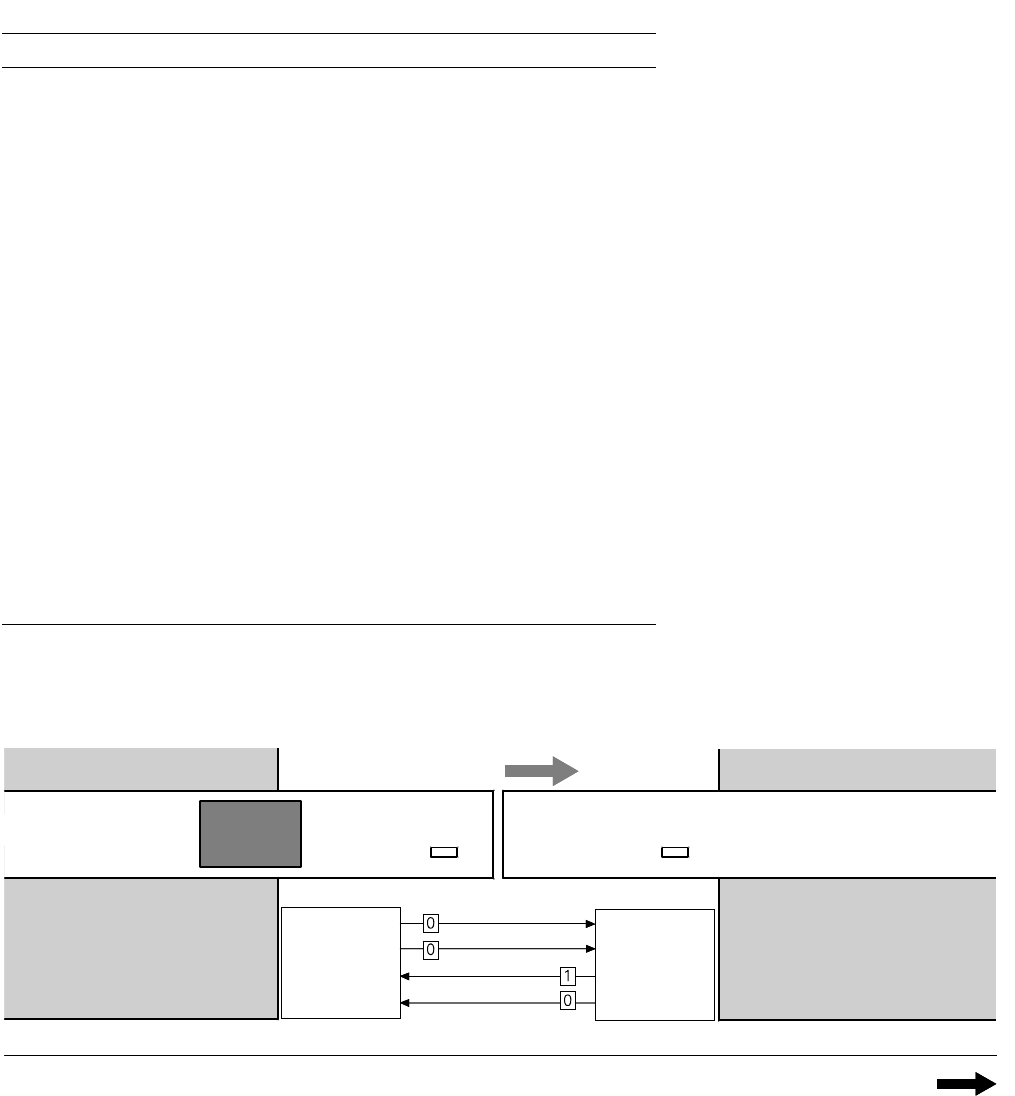
1. After switching-on the station
Technical Data:
Signal Interfaces
Signal Interface (20-Pin Ribbon Cable Connector)
to upstream station x3 to downstream station x4
Pin 13 GND 24 V Pin 10 Reserved
Pin 14 Arrived Pin 9 Reserved
Pin 15 Permission Pin 8 Reserved
Pin 19 Request Pin 4 +30 V DC
unsaturated
Pin 20 GND 24 V for request / re-
leased (contact separation)
Pin 5 GND 24 V
Pin 18 Released Pin 6 +24 V DC
Pin 12 Trouble signal loop Pin 11 Trouble signal loop
Pin 11 Pin 12
Pin 3 +24 V DC Pin 15 Permission
Pin 2 GND 24 V Pin 13 GND 24 V for per-
mission / arrived
(contact separation)
Pin 1 +30 V DC unsaturated Pin 14 Arrived
Pin 8 Reserved Pin 18 Released
Pin 9 Reserved Pin 19 Released
Pin 10 Reserved Pin 20 GND 24 V
Requirement
Delivery
Permission
Receival
Requirement
Delivery
Permission
Receival
Transport Direction
Conveyor Section 1
PCB
Sensor
PCB
Sensor
Conveyor Section 2
Station n
transports
PCB
to delivery
Station n+1
is ready to
receive PCBs
Conveyor 1 is On Conveyor 2 is Off