Specification SIPLACE CS-Speed - 第28页
26 Left Side (Gantry 1) Right Side (Gantry 2) 6-Nozzle Co llect & P lace Head 6-Noz zle Co llect & Pl ace Head Reject B in Changeover T able with 20 feeder locations for Tapes , Sticks and B ulk Nozzle Changer No…
25
Description
Transporting
TransportingTransporting
Transporting
Use a fork lift with a lifting force
of 6 tons to move the SIPLACE CS
placement machine. Forks 2 m
long are required for a packed ma-
chine, 1.5 m for an unpacked one.
Pick the machine up with the fork
lift at the locations especially de-
signed and identified as being for
this purpose.
When setting up the SIPLACE CS,
make certain that the surface it is
placed on possesses the required
load bearing capacity.
Commissioning
CommissioningCommissioning
Commissioning
For commissioning, install the fol-
lowing components which were
not premounted upon delivery:
§ Monitor
§ Keyboard
§ Warning lamp
§ Component changeover tables.
Technical Data:
Transporting and Commissioning
Transport dimensions
Length with packing
Width with packing
Height with packing
2150 mm
1850 mm
1600 mm
Center of gravity (X,Y coordinates) 0 mm, 0 mm
Floor load (more details about floor characteristics on request)
Total weight of equipped machine 2 metric tons
Permissible surface load sub-floor
(load per unit area on mounting feet)
(based on assumed distribution of
machine weight to three machine legs
a
)
9 kg/cm
2
a) Worst case scenario; 4 legs per machine installed, area per leg: 104 cm
2
.
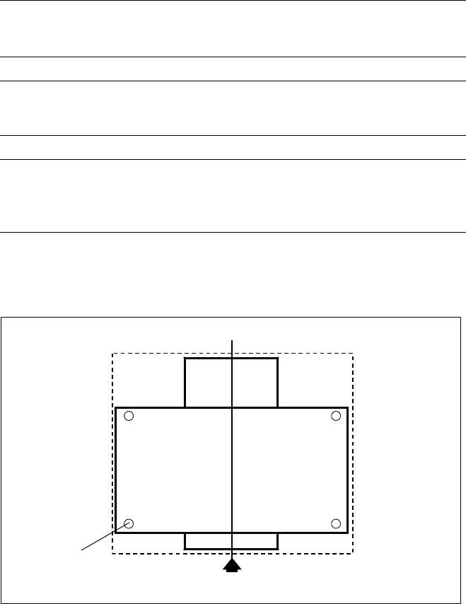
SIPLACE CS with Transportbox
Footprints
PCB Transport Direction
Dimension of
Transport Box
26
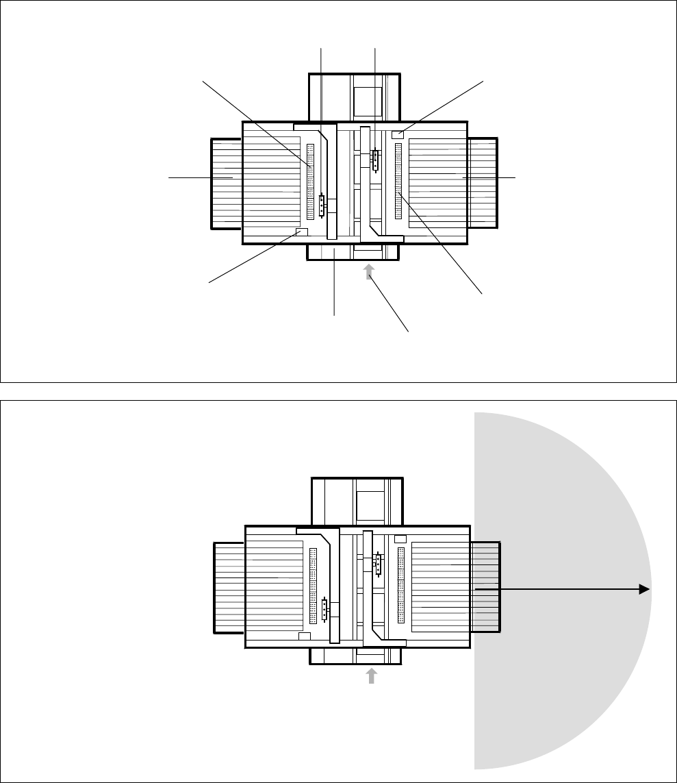
Left Side (Gantry 1) Right Side (Gantry 2)
6-Nozzle Collect & Place Head 6-Nozzle Collect & Place Head
Reject Bin
Changeover Table with
20 feeder locations for
Tapes, Sticks and Bulk
Nozzle Changer
Nozzle Changer
Changeover Table with
20 feeder locations for
Tapes, Sticks and Bulk
Reject Bin
3-Section Conveyor with automatic
width adjustment for PCBs from
50 x 50 mm
2
up to 508 x 460 mm
2
( 2" x 2" up to 20" x 18" )
PCB Transport
Direction
1.20 m
Possible Machine Configuration
Shunting Radius for
Changeover Table
1.20 m
PCB Transport Direction
27