Specification SIPLACE CS-Speed - 第4页
2 Speed Placement System for Medium Volume SIPLACE CS SIPLACE C S
1
Subject to change
without notice.
Edition 1
0403-CS-e
Order No
A10002-P141-T4-X-7600
Machine Description 3
Line Design 4
Placement Heads 5
6-Nozzle Collect & Place Head for High Speed
Component Placement
Placement Accuracy
Component Range
Nozzle Changer
PCB Conveyor 8
Component Supply 9
Changeover Table
Tape Feeder
Bulk Case Feeder
Stick Magazine Feeder
Guard for Feeder Locations
Component Bar Code Scanner for Set-Up and Refill Check
(Option)
SIPLACE External Set-Up Station (Option)
Vision Sensor Technology 15
PCB Vision Module
PCB Position Recognition
Bad Board Recognition
Position Recognition of Feeder
Standard Component Vision Modules for 6-Nozzle
Collect & Place Head
Machine Criteria 19
Mapping (Option)
SIPLACE Software Architecture 20
Line Programming System
Station Computer
Technical Data 21
Signal Interfaces
Connections
Dimensions and Set-Up Conditions
Transporting and Commissioning
Possible Machine Configuration 26
Speed Placement System for Medium Volume
SIPLACE CS
2
Speed Placement System for Medium Volume
SIPLACE CS
SIPLACE CS

3
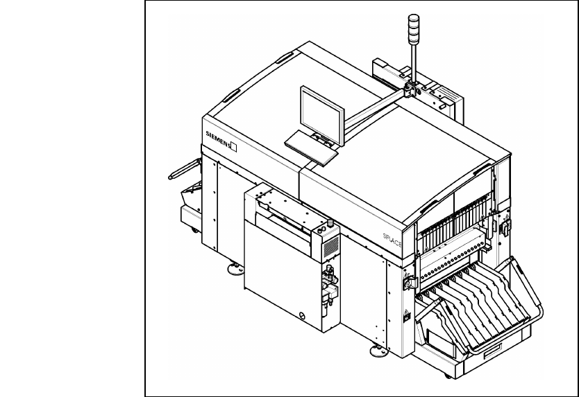
Description
SIPLACE CS placement machines
combine placement speed with
flexibility and accuracy.
SIPLACE CS is equipped with two
X-/Y-main gantries. Each gantry
features a star-shaped Collect
& Place placement head with
6 nozzles. The first components
are already being picked up while
the PCB is being moved in.
While one Collect & Place Head
is placing components, the other
one is picking up components.
The placement heads alternately
pick up components from the sta-
tionary component feeder and
place components on the PCB
which is also motionless.
This award winning SIPLACE
concept has distinct advantages:
§ Component tapes can be re-
plenished by splicing a new reel
of components to the end of a
depleting reel. This eliminates
machine stoppage due to com-
ponent replenishment.
§ Stationary, vibration-free feed-
ers ensure a reliable pick-up of
even the smallest components
(e.g., 0201).
§ Thanks to the flexibility of the
Collect & Place Heads – whose
ideal nozzle set-up is automatically
specified – the path can be mini-
mized and the sequence of place-
ment optimally adjusted.
§ Populating a stationary PCB also
prevents components from
shifting during placement.
Automatic width adjustment, auto-
matic nozzle changers, easy chang-
ing of feeder modules or change-
over tables, which can be replaced
within minutes, allow quick changes
of productions.
The following options are available
for the SIPLACE CS:
§ Additional changeover tables
enables the reduction of job set-
up time increasing machine
utilisation.
§ Component Bar Code Scanner
used for feeder set-up verifica-
tion.
Machine Description
Technical Data
Type of placement head 6-Nozzle Collect & Place Head
Number of gantries 2
Benchmark placement rate
a
20,000 cph
Component Range 0.6 x 0.3 mm
2
(0201) to 18.7 x 18.7 mm
2
Max. placement accuracy
(at 4 sigma)
a
90 µm
PCB dimensions
(L x W)
50 x 50 mm
2
to 508 x 460 mm
2
/
2" x 2" to 20" x 18"
Feeding capacity 118 tracks, 8 mm tape
Component table Quick changeover table with integrated
wheels, reel holder, scrap bin, cutting tool
Types of Feeder modules Tapes, Bulk Cases, Stick Magazines,
Operating system Microsoft Windows / RMOS
Power 1,9 kW
Compr. air requirements 5.5 - 10 bar, 400 Nl/min, tube ½"
Standard configuration Nozzle changer
Feeder package
SMEMA
a) As defined in Scope of Service and Delivery SIPLACE.