Specification SIPLACE CS-Speed - 第6页
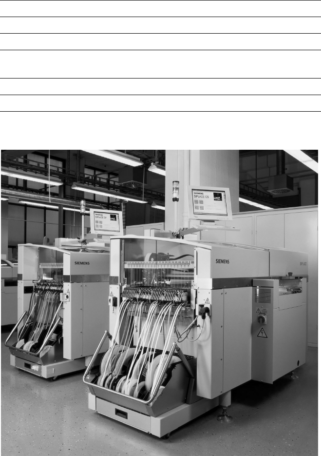
4 Example of a P lacement Line of SIPLACE Compact machi nes Description Flexib ility an d adapt ability cha- racterize the modular SIPLACE design. Each production line can be individually composed of simila r and differe…

3
Description
SIPLACE CS placement machines
combine placement speed with
flexibility and accuracy.
SIPLACE CS is equipped with two
X-/Y-main gantries. Each gantry
features a star-shaped Collect
& Place placement head with
6 nozzles. The first components
are already being picked up while
the PCB is being moved in.
While one Collect & Place Head
is placing components, the other
one is picking up components.
The placement heads alternately
pick up components from the sta-
tionary component feeder and
place components on the PCB
which is also motionless.
This award winning SIPLACE
concept has distinct advantages:
§ Component tapes can be re-
plenished by splicing a new reel
of components to the end of a
depleting reel. This eliminates
machine stoppage due to com-
ponent replenishment.
§ Stationary, vibration-free feed-
ers ensure a reliable pick-up of
even the smallest components
(e.g., 0201).
§ Thanks to the flexibility of the
Collect & Place Heads – whose
ideal nozzle set-up is automatically
specified – the path can be mini-
mized and the sequence of place-
ment optimally adjusted.
§ Populating a stationary PCB also
prevents components from
shifting during placement.
Automatic width adjustment, auto-
matic nozzle changers, easy chang-
ing of feeder modules or change-
over tables, which can be replaced
within minutes, allow quick changes
of productions.
The following options are available
for the SIPLACE CS:
§ Additional changeover tables
enables the reduction of job set-
up time increasing machine
utilisation.
§ Component Bar Code Scanner
used for feeder set-up verifica-
tion.
Machine Description
Technical Data
Type of placement head 6-Nozzle Collect & Place Head
Number of gantries 2
Benchmark placement rate
a
20,000 cph
Component Range 0.6 x 0.3 mm
2
(0201) to 18.7 x 18.7 mm
2
Max. placement accuracy
(at 4 sigma)
a
90 µm
PCB dimensions
(L x W)
50 x 50 mm
2
to 508 x 460 mm
2
/
2" x 2" to 20" x 18"
Feeding capacity 118 tracks, 8 mm tape
Component table Quick changeover table with integrated
wheels, reel holder, scrap bin, cutting tool
Types of Feeder modules Tapes, Bulk Cases, Stick Magazines,
Operating system Microsoft Windows / RMOS
Power 1,9 kW
Compr. air requirements 5.5 - 10 bar, 400 Nl/min, tube ½"
Standard configuration Nozzle changer
Feeder package
SMEMA
a) As defined in Scope of Service and Delivery SIPLACE.
4
Example of a Placement Line of SIPLACE Compact machines
Description
Flexibility and adaptability cha-
racterize the modular SIPLACE
design. Each production line can
be individually composed of
similar and different modules.
Because of the small size and ro-
bust construction of the SIPLACE
modules, they can be recombined
quickly and easily to accommodate
changes in production requirements.
SIPLACE line-level optimization
tools generate single set-ups for
single products or for several
products. Also, product programs
can be transferred from line to line
even when the machine configura-
tions are different.
The innovative SIPLACE platform,
with its cutting-edge technology,
guarantees maximum productivity,
while compatibility across several
machine generations ensures you
of long-term investment protection.
And with SIPLACE, you benefit
from a global support network with
29 locations in Europe, 32 locations
in the Americas, and 23 locations in
Asia.
Line Design
Technical Data
System SIPLACE SMD placement lines
Modules SIPLACE CS / SIPLACE CF
PCB conveyor Automatic width adjustment
PCB dimensions
(L x W)
50 x 50 mm
2
to 508 x 460 mm
2
/
2" x 2" to 20" x 18"
Placement speed Depends on layout of modules
Space required 4 m² / SIPLACE CS & CF modules
5
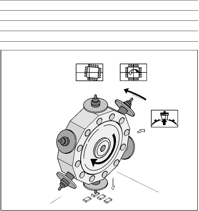
6-Nozzle Collect & Place Head for High Speed Placement
Component Pick-Up/
Placement
Segment
Removal
Point
Turning to
the Placement
Position
Component
Vision
Description
The 6-Nozzle placement head
operates on the Collect & Place
principle. In contrast to classic
chip shooters, the 6 vacuum
nozzles of the SIPLACE Collect
& Place head rotate around a
horizontal axis. This does not
only save space:
Due to the small diameter com-
pared to chip shooters, the cen-
trifugal forces are significantly
lower. The results are high-speed,
reliable placement and the same
cycle time for all components.
Components are picked up and
placed reliably with the aid of vac-
uum followed by a gentle air kiss.
A number of vacuum tests moni-
tors if the component has been
picked up and placed accurately.
Various control and self-learning
functions further enhance the de-
pendability of the system:
§ The optical recognition of feeder
positions records the exact posi-
tion of the feeder table.
§ A camera on the placement head
(component vision module) de-
termines the exact position of
each component on the nozzle.
§ For every feeder the pick-up
offsets are averaged over the
last ten pick-ups. This enables
the head to dial-in on the pre-
cise pick point for each compo-
nent.
§ In addition, the package form is
also checked. If the actual geo-
metric dimensions of the com-
ponent do not correspond to
those programmed, the compo-
nent is rejected.
§ Components rejected by the
vision system are dumped into
a bin. Any rejected component
gets automatically placed during
a repair run.
§ Warpage of the PCB is accom-
modated by sensor stop acti-
vated z-axis placement. The sys-
tem also keeps the last ten
positions of the z-axis at com-
ponent placement and uses the
average of these values to im-
prove the drive down and place
speed of the cycle.
Placement Heads:
6-Nozzle Collect & Place Head for High Speed
Component Placement
Technical Data
Benchmark placement rate See table on page 3
Stroke of Z-axis max. 16 mm
Programmable placement force 2.4 to 5.0 N
Accuracy and Component range See table on page 6