Specification SIPLACE CS-Speed - 第8页
6 Placement Heads: Placement Accuracy Component Range Placement A ccuracy a Placement Head Placement Accurac y 6-Nozzle Collect & Place Head X/Y Accuracy ± 67.5 µm 3 Sigma Rot.-Acc uracy ± 0.525° X/Y Accuracy ± 90.0 …
5
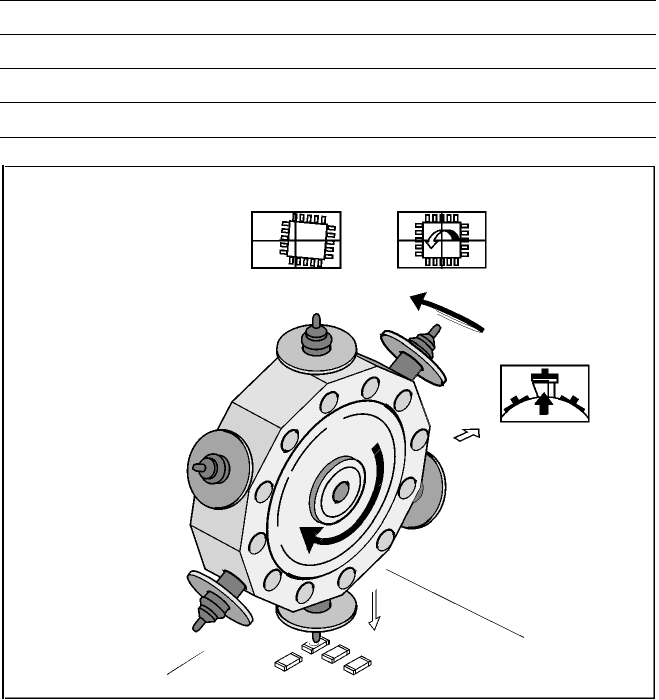
6-Nozzle Collect & Place Head for High Speed Placement
Component Pick-Up/
Placement
Segment
Removal
Point
Turning to
the Placement
Position
Component
Vision
Description
The 6-Nozzle placement head
operates on the Collect & Place
principle. In contrast to classic
chip shooters, the 6 vacuum
nozzles of the SIPLACE Collect
& Place head rotate around a
horizontal axis. This does not
only save space:
Due to the small diameter com-
pared to chip shooters, the cen-
trifugal forces are significantly
lower. The results are high-speed,
reliable placement and the same
cycle time for all components.
Components are picked up and
placed reliably with the aid of vac-
uum followed by a gentle air kiss.
A number of vacuum tests moni-
tors if the component has been
picked up and placed accurately.
Various control and self-learning
functions further enhance the de-
pendability of the system:
§ The optical recognition of feeder
positions records the exact posi-
tion of the feeder table.
§ A camera on the placement head
(component vision module) de-
termines the exact position of
each component on the nozzle.
§ For every feeder the pick-up
offsets are averaged over the
last ten pick-ups. This enables
the head to dial-in on the pre-
cise pick point for each compo-
nent.
§ In addition, the package form is
also checked. If the actual geo-
metric dimensions of the com-
ponent do not correspond to
those programmed, the compo-
nent is rejected.
§ Components rejected by the
vision system are dumped into
a bin. Any rejected component
gets automatically placed during
a repair run.
§ Warpage of the PCB is accom-
modated by sensor stop acti-
vated z-axis placement. The sys-
tem also keeps the last ten
positions of the z-axis at com-
ponent placement and uses the
average of these values to im-
prove the drive down and place
speed of the cycle.
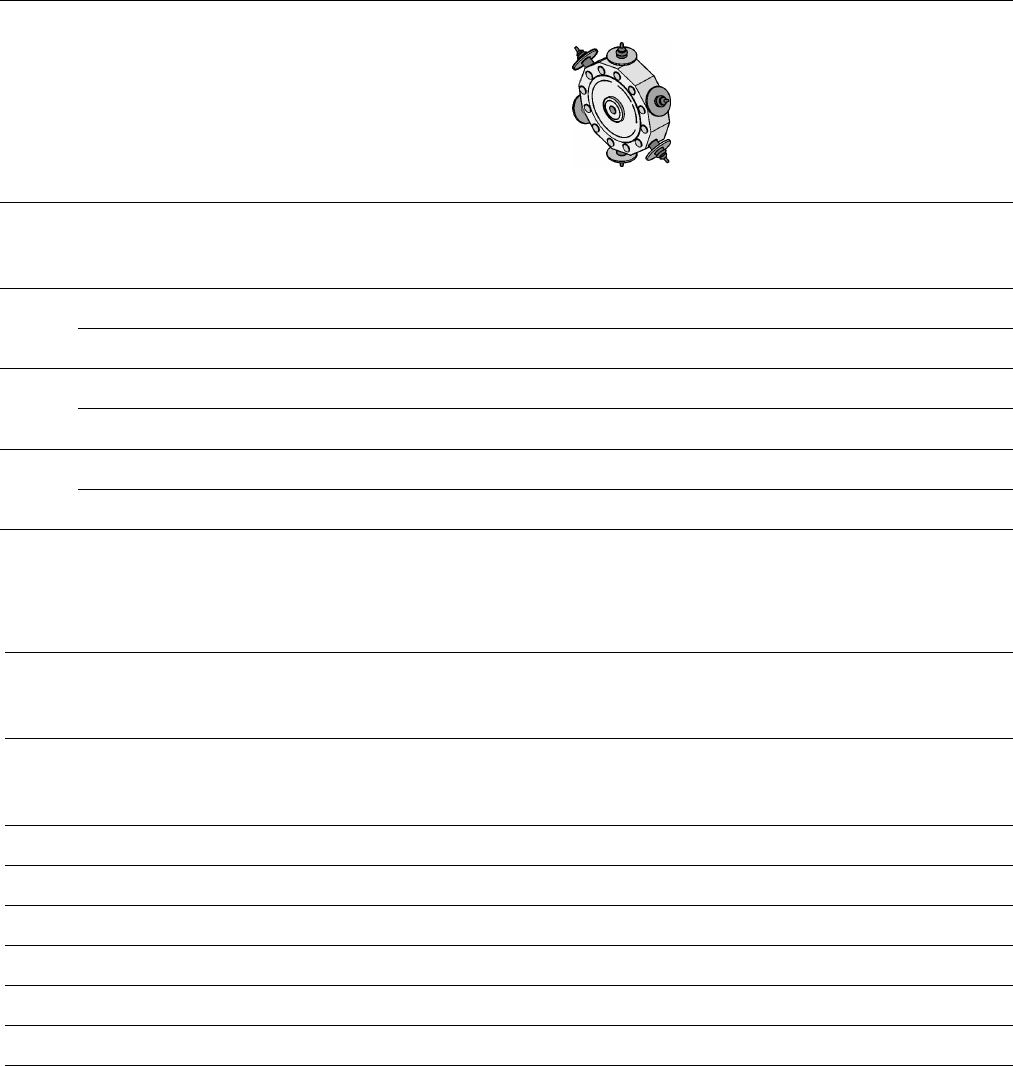
Placement Heads:
6-Nozzle Collect & Place Head for High Speed
Component Placement
Technical Data
Benchmark placement rate See table on page 3
Stroke of Z-axis max. 16 mm
Programmable placement force 2.4 to 5.0 N
Accuracy and Component range See table on page 6
6
Placement Heads:
Placement Accuracy
Component Range
Placement Accuracy
a
Placement Head
Placement Accuracy
6-Nozzle
Collect & Place Head
X/Y Accuracy ± 67.5 µm
3
Sigma
Rot.-Accuracy ± 0.525°
X/Y Accuracy ± 90.0 µm
4
Sigma
Rot.-Accuracy ± 0.700°
X/Y Accuracy ± 135.0 µm
6
Sigma
Rot.-Accuracy ± 1.050°
a) As defined in Scope of Service and Delivery SIPLACE.
Component Range
6-Nozzle
Collect & Place Head
Component size
0.6 x 0.3 mm
2
b
to
18.7 x 18.7 mm
2
Max. component height 6 mm
Max. component weight 2 gr
Placement force 2.4 - 5.0 N
Performance See table on page 3
Min. pitch lead / bump 500 / 350 µm
Min. ball / bump diam. 200 µm
b) 0201 (recommended to order the special 0201-kit).
7
Description
A nozzle changer corresponding to
the Collect & Place Head in use
can be installed to the left of the
PCB conveyor with no loss of
feeder capacity. It will change the
nozzle set-up of the placement
head quickly and reliably for the
specific nozzle configuration valid
to a job. Damaged or faulty nozzles
can be exchanged via the menu
function on the station computer.
Placement Heads:
Nozzle Changer
Technical Data
6-Nozzle Collect & Place Head
Type of nozzle All standard nozzles of nozzle series 7xx/9xx
(special nozzles must be tested individually)
Capacity 5 magazines, each with 6 nozzles of one
nozzle series
Nozzle changing times About 2 s per nozzle
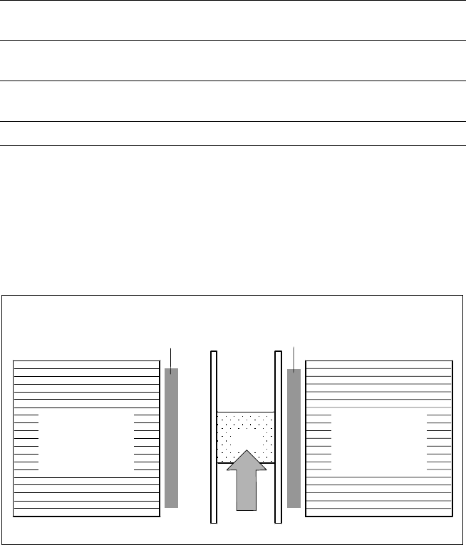
Position of Nozzle Changers
Component
Feeders for
Collect & Place
Head
PCB
Nozzle Changer for 6-Nozzle Collect & Place Head
(5 Magazines, each with 6 Nozzles, Option)
Component
Feeders for
Collect & Place
Head