MR8740T_user_manual_eng_20191016H.pdf - 第120页
11 5 T riggering the Instrument With Logic Signals (Logic T rigger) 3 Click each of the signals under [T rigger pattern] to set a logic-trigger pattern. The logic-trigger pattern can be set. X Ignores a signal. 0 The l…
114
Triggering the Instrument With Logic Signals (Logic Trigger)
5.7 Triggering the Instrument With Logic Signals
(Logic Trigger)
This section explains how to congure the logic trigger settings.
• Input signals acquired across the logic channels serve as a trigger source.
• You can set a trigger pattern and trigger logical-condition by choosing between logical AND and
OR operations. When the logic-trigger conditions are satised, a logic trigger is generated.
• With the trigger lter setting, no logic triggers are generated until the logic-trigger condition is
continuously satised during the specied lter width or more.
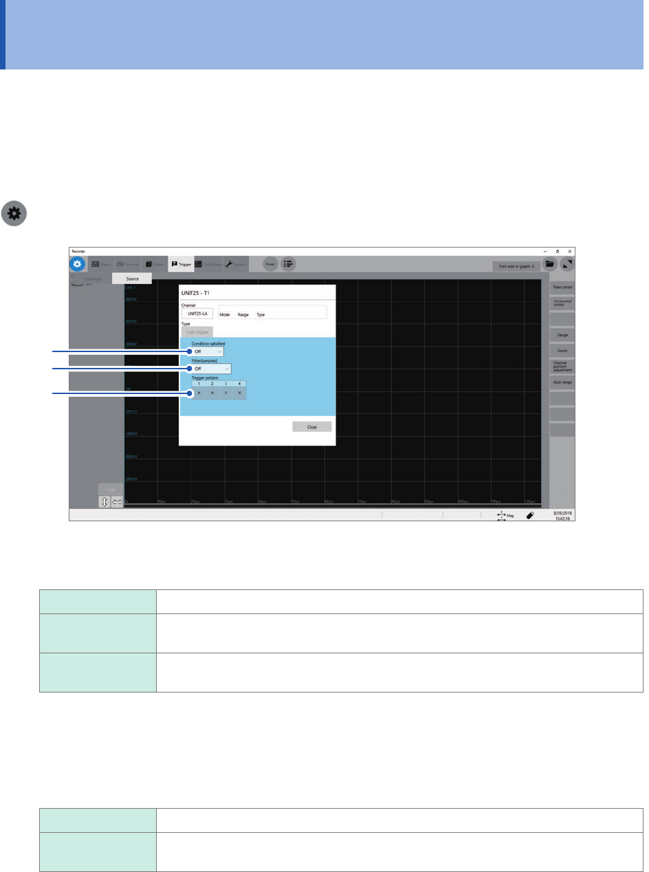
> [Trigger] > [Source]
2
3
1
1
Click the [Condition satised] box, and then choose a logic-trigger satisfaction condition
from the list.
Off
Disables the logic trigger.
OR The logic-trigger condition is satised when any one of logic input signals matches the
trigger pattern.
AND The logic-trigger condition is satised when all logic input signals match the trigger
pattern.
2
Click the [Filter] box, and then choose a sampling count of the lter from the list.
Only after the level-trigger condition is continuously satised during the specied period, an analog trigger is
generated.
Conguring the trigger lter setting prevents a logic trigger from being unintentionally generated due to noise.
(p. 107)
Off
Disables the trigger lter.
10 to 10000 Enables the trigger lter.
Allows you to enter a lter width in the number of samples.
115
Triggering the Instrument With Logic Signals (Logic Trigger)
3
Click each of the signals under [Trigger pattern] to set a logic-trigger pattern.
The logic-trigger pattern can be set.
X
Ignores a signal.
0 The logic-trigger condition of each logic signal is satised when the signal is at a low
level.
1 The logic-trigger condition of each logic signal is satised when the signal is at a high
level.
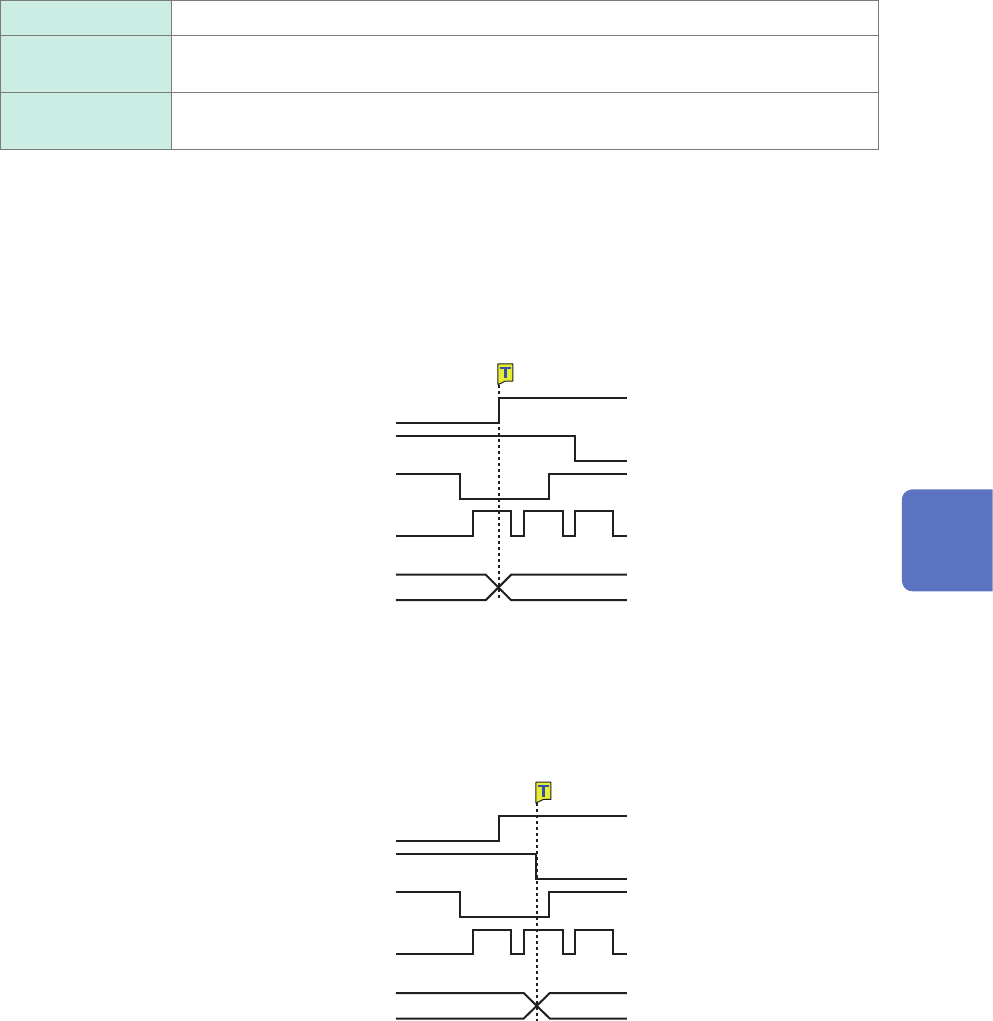
Setting example
The logic-trigger conditions differ depending on the combination of the [Condition satised]
setting (logical OR or AND operation) and the [Trigger pattern] setting as follows:
Lx1 [1]
Lx2 [0]
Lx3 [X]
Lx4 [X]
Lx1 [1]
Lx2 [0]
Lx3 [X]
Lx4 [X]
OR
AND
Trigger pattern
Trigger pattern
Not satised Satised
Not satised Satised
Logic-trigger condition
Logic-trigger condition
5
Conguring the Trigger Settings
116
Triggering the Instrument at Regular Intervals (Interval Trigger)
5.8 Triggering the Instrument at Regular Intervals
(Interval Trigger)
Start triggers can be activated at specied intervals. Setting the recording mode to [Repeat] allows
the instrument to record waveforms at regular intervals.
• When using the pre-trigger, the instrument starts monitoring interval-trigger times after the rst
pre-trigger time elapses since the start of measurement.
• No start triggers are activated by any interval triggers while the instrument is lling the pre-trigger
memory. An interval trigger triggers the instrument while the instrument is waiting for a trigger
after the instrument has lled the pre-trigger memory.
• Since the clock is internally corrected, displayed trigger times may not synchronize with the
intervals of the interval trigger.
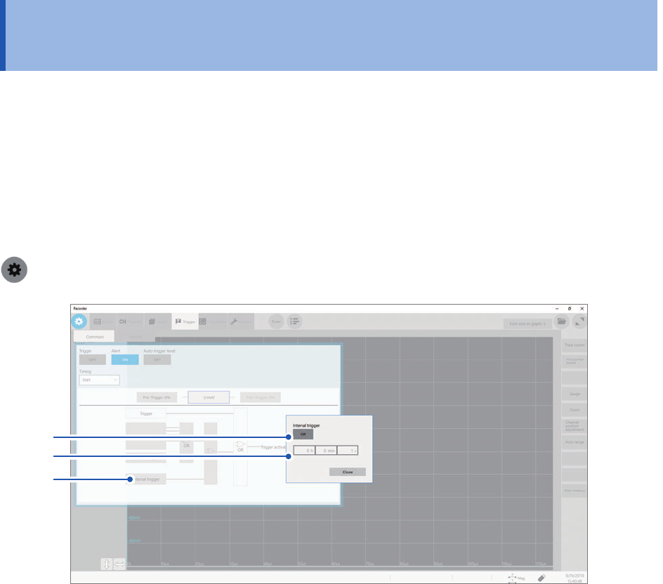
> [Trigger] > [Common]
2
3
1
1
Click [Interval trigger].
The interval trigger setting dialog box will appear.
2
Click [Interval trigger] to set it to [On].
3
Click the [h], [min], and [s] boxes, and then enter a period of time for interval triggers.
An internal trigger is generated at the start of measurement, and triggers are repeatedly generated at the
specied intervals.