MR8740T_user_manual_eng_20191016H.pdf - 第16页
11 Conguring the Input Channel settings Analog channels For details on conguring each module setting, refer to “3.6 Conguring Measuring-Module-Specic Settings” (p. 46). > [Channel] > each module (UNIT) 2 1 4 5 …
10
Conguring the Input Channel settings
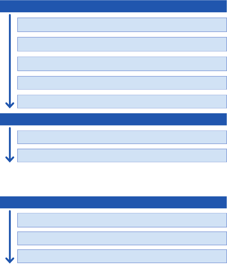
Channel setting procedure
Analog channels (CH1 through CH108) setting procedure
Conguring the input settings
Choose a measurement mode.
(p. 11)
Choose a measurement range for each measurement target.
(p. 12)
Convert input values (scaling function).
(p. 14)
Choose an input coupling method.
(p. 13)
Choose a low-pass lter cutoff frequency (if noise is present).
(p. 13)
Conguring the display settings
Select a waveform color.
(p. 14)
Convert input values (scaling function).
(p. 14)
Logic channels (Model 8973 Logic Unit) setting procedure
Conguring the display settings
Choose a logic recording width.
(p. 15)
Specify the display position of the waveform.
(p. 15)
Select a waveform color.
(p. 15)
11
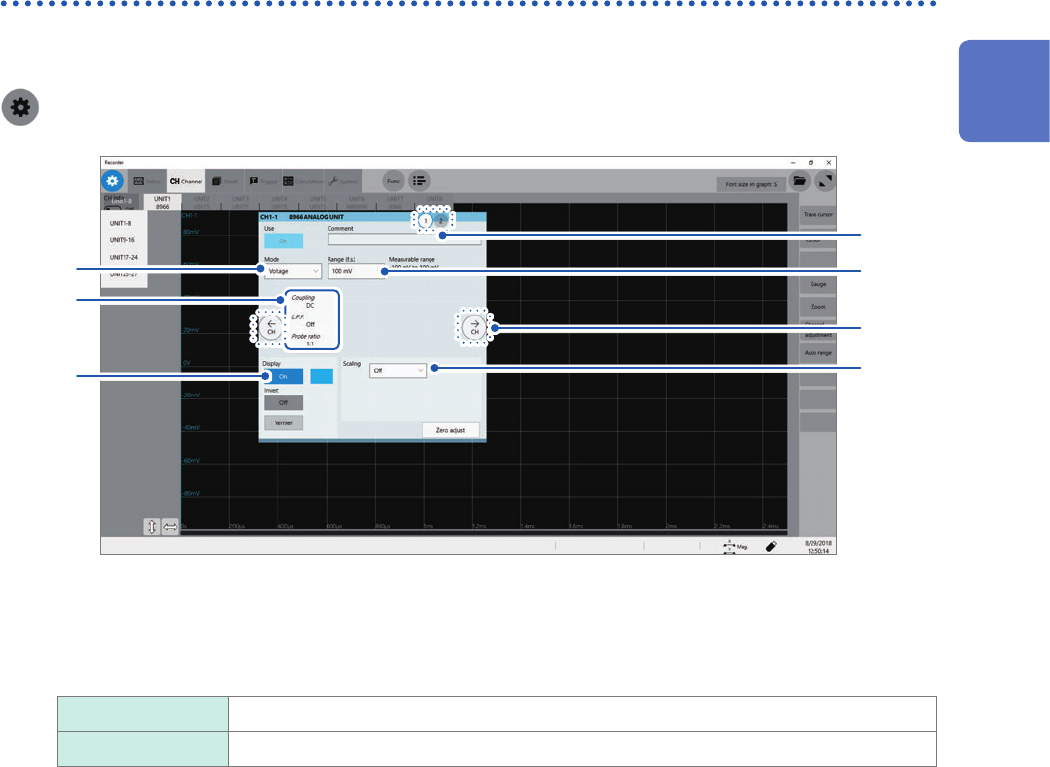
Conguring the Input Channel settings
Analog channels
For details on conguring each module setting, refer to “3.6 Conguring Measuring-Module-Specic
Settings” (p. 46).
> [Channel] > each module (UNIT)
2
1
4
5
7
3
6
1
Enter a comment in the [Comment] box.
Number of characters that can be entered: up to 40
2
Click the [Mode] box, and then choose a measurement mode from the list.
Voltage
Measures a waveform in voltage mode.
Temperature Measures a waveform in temperature mode.
Selectable modes vary depending on the installed modules.
Refer to “3.6 Conguring Measuring-Module-Specic Settings” (p. 46).
1
Measurement Method
12
Conguring the Input Channel settings
3
Click the [Range (f.s.)] box, and then choose a measurement range from the list.
Select a measurement range for each channel. The value of the range represents its maximum displayable
value (f.s.).
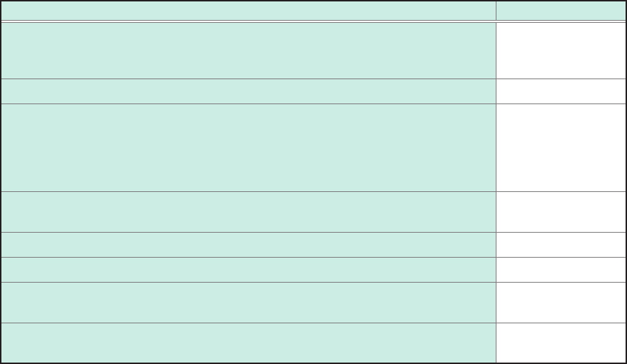
See the following table for the full-scale resolution of each module.
If the input voltage exceeds the measurable range (overrange occurs), change the measurement range to one
with a lower sensitivity.
For Model MR8990 and Model U8991, starting a measurement using a high-sensitivity range with the input
terminal open causes an input signal to be overrange.
After changing the measurement range, check values of the level, upper limit, lower limit, and other values of
the trigger, search, and numerical calculation functions.
Module Resolution (LSB)
Model 8966 Analog Unit
Model 8971 Current Unit
Model 8972 DC/RMS Unit
2,000
Model 8967 Temp Unit* 20,000
Model 8968 High Resolution Unit
Model U8974 High Voltage Unit
Model U8975 4ch Analog Unit
Model U8977 3CH Current Unit
Model U8978 4CH Analog Unit
32,000
Model U8969 Strain Unit
Model U8979 Charge Unit
25,000
Model 8970 Freq Unit (Power frequency mode) 2,000
Model 8970 Freq Unit (Count mode) 40,000
Model 8970 Freq Unit
(Frequency mode, rotation speed mode, duty ratio mode, pulse width mode)
10,000
Model MR8990 Digital Voltmeter Unit
Model U8991 Digital Voltmeter Unit
1,000,000
*: For the Model 8967 Temp Unit, the valid range varies depending on the thermocouples. For more
information about resolution, refer to “Model 8967 Temp Unit” in “5.2 Specications of the Options” in Quick
Start Manual.