MR8740T_user_manual_eng_20191016H.pdf - 第216页
2 11 External Input and Output 4 Connect the terminal to GND. Otherwise, input pulse waves or rectangular waves to the terminal. The signal shall have a high-level voltage of between 2.5 V and 10 V and a l ow-level volta…
210
External Input and Output
12.1 External Input and Output
External input (IN1), (IN2)
Externally inputting signals can start and stop measurement as well as save data.
In factory default settings, the START signal is assigned to the IN1, and the STOP signal to the IN2
terminal.
How to input signals
1
Connect each of the IN1, IN2, and GND terminals to an external signal-outputting device with
wires.
Refer to “2.3 Connecting the External Control Terminals” in Quick Start Manual.
2
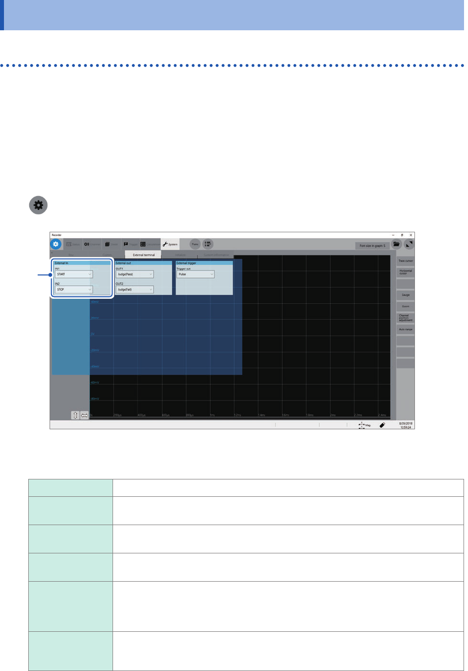
> [System] > [External terminal]
3
3
Click the [IN1] and [IN2] boxes in the [External In] area in turn, and then from the list, choose
an action performed when an input signal is inputted.
START Starts a measurement.
STOP Stops the measurement (post-measurement processes such as numerical calculations
and automatic saving are performed).
START/STOP Starts a measurement when the low-level signal is inputted; stops the measurement
when the high-level signal is inputted.
SAVE Saves data on the specied conditions into a storage device that is specied in ([Status]
> [Save] > [Save Icon operation] >) [Quick].
ABORT Forcibly terminates the measurement. (No post-measurement processes such as
numerical calculations or automatic saving are performed. However, the instrument
automatically saves a waveform le that contains data acquired until the forcible
termination)
EVENT Puts on an event mark.
The event marks are put on the waveform screen.
You can put event marks by clicking the start icon during a measurement.
211
External Input and Output
4
Connect the terminal to GND.
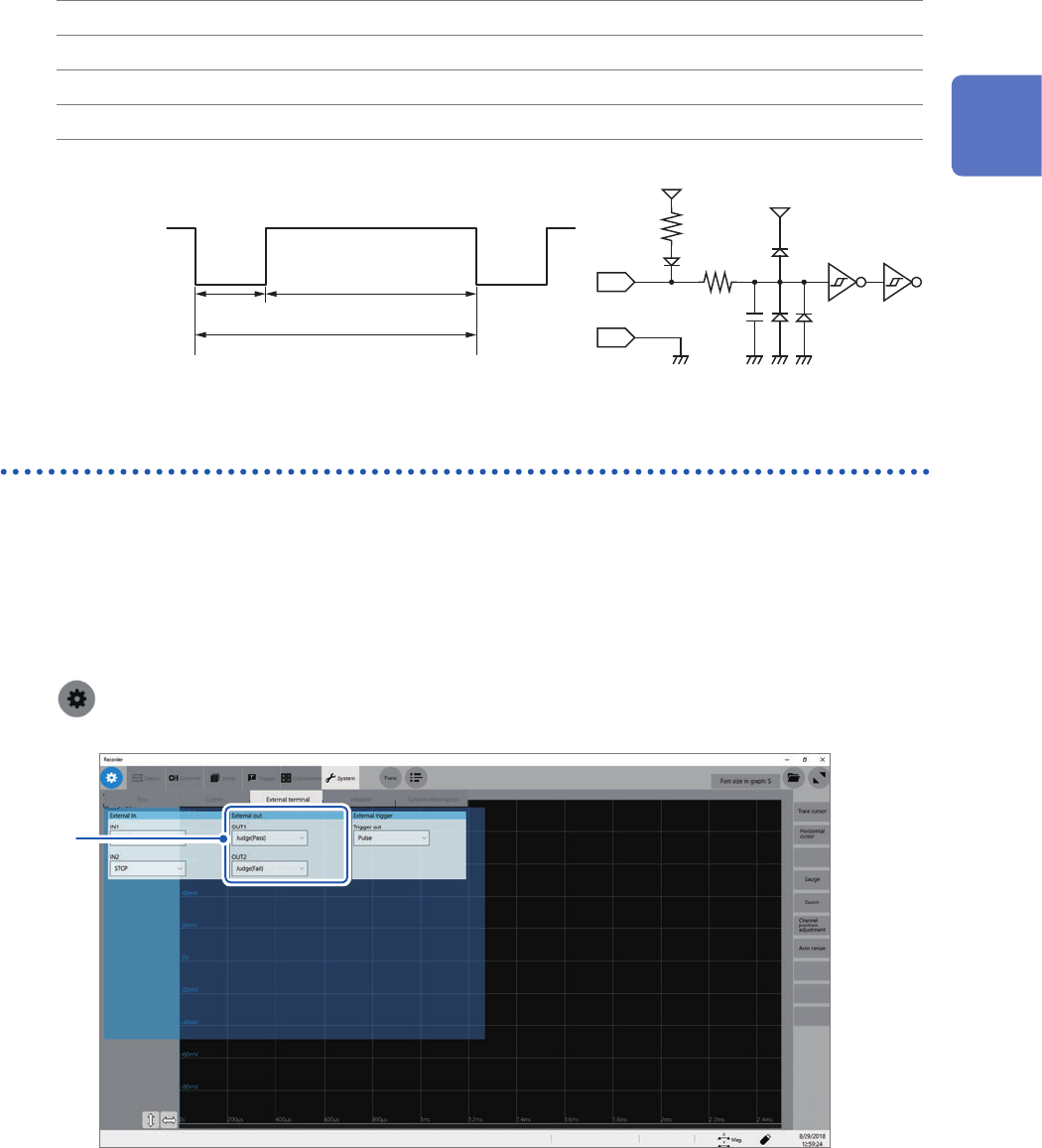
Otherwise, input pulse waves or rectangular waves to the terminal. The signal shall have a
high-level voltage of between 2.5 V and 10 V and a low-level voltage of between 0 V and 0.8 V.
The low level of the input waveform activate the input circuit, controlling the instrument.
Available voltage range High level: 2.5 V to 10 V; low level: 0 V to 0.8 V
Pulse width High-level period: 50 ms or more; low-level period: 50 ms or more
Pulse interval 200 ms or more
Maximum input voltage 10 V DC
IN1
IN2
100 kΩ
GND
100 pF
5 V
3 kΩ
5 V
High
2.5 V to 10 V
Low
0 V to 0.8 V
50 ms or more 50 ms or more
200 ms or more
External output (OUT1), (OUT2)
The instrument can output various signals depending on its state.
How to output signals
1
Connect each of the OUT1, OUT2, and GND terminals to an external signal-inputting device
with wires.
Refer to “2.3 Connecting the External Control Terminals” in Quick Start Manual.
2
> [System] > [External terminal]
3
12
Externally Controlling the Instrument
212
External Input and Output
3
Click the [OUT1] and [OUT2] boxes in the [External out] area in turn, and then from the list,
choose a signal output action.
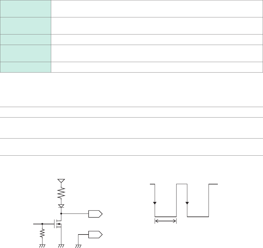
Choose a condition where the instrument outputs a signal.
Judge(Pass) Outputs a low-level signal when a pass judgment is given for the numerical calculation
result.
Judge(Fail) Outputs a low-level signal when a fail judgment is given for the numerical calculation
result.
Error Outputs a low-level signal when an error occurs.
Busy Outputs a low-level signal while rejecting a START signal because the instrument is in
the busy state such as performing a measurement and saving data.
Waiting trigger Outputs a low-level signal while waiting for a trigger.
The instrument continuously outputs the signal for a pass/fail judgment (low-level output) until it starts the next
measurement.
The instrument can output various signals depending on its state.
Output signal Open-drain output (with voltage output), active low
Output voltage
range
High level: 4.0 V to 5.0 V
Low level: 0 V to 0.5 V
Maximum input
voltage
50 V DC, 50 mA, 200 mW
GND
OUT1
OUT2
100
kΩ
10 kΩ
5 V
High
4.0 V to 5.0 V
Low
0 V to 0.5 V
Output period