MR8740T_user_manual_eng_20191016H.pdf - 第217页
212 External Input and Output 3 Click the [OUT1] and [OUT2] boxes in the [External out] area in turn, and then from the list, choose a signal output action. Choose a condition where the instrument outputs a signal. Judge…
211
External Input and Output
4
Connect the terminal to GND.
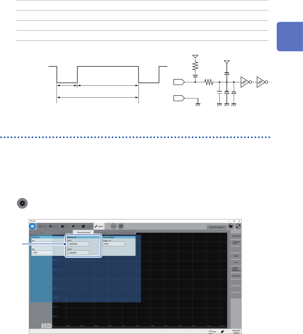
Otherwise, input pulse waves or rectangular waves to the terminal. The signal shall have a
high-level voltage of between 2.5 V and 10 V and a low-level voltage of between 0 V and 0.8 V.
The low level of the input waveform activate the input circuit, controlling the instrument.
Available voltage range High level: 2.5 V to 10 V; low level: 0 V to 0.8 V
Pulse width High-level period: 50 ms or more; low-level period: 50 ms or more
Pulse interval 200 ms or more
Maximum input voltage 10 V DC
IN1
IN2
100 kΩ
GND
100 pF
5 V
3 kΩ
5 V
High
2.5 V to 10 V
Low
0 V to 0.8 V
50 ms or more 50 ms or more
200 ms or more
External output (OUT1), (OUT2)
The instrument can output various signals depending on its state.
How to output signals
1
Connect each of the OUT1, OUT2, and GND terminals to an external signal-inputting device
with wires.
Refer to “2.3 Connecting the External Control Terminals” in Quick Start Manual.
2
> [System] > [External terminal]
3
12
Externally Controlling the Instrument
212
External Input and Output
3
Click the [OUT1] and [OUT2] boxes in the [External out] area in turn, and then from the list,
choose a signal output action.
Choose a condition where the instrument outputs a signal.
Judge(Pass) Outputs a low-level signal when a pass judgment is given for the numerical calculation
result.
Judge(Fail) Outputs a low-level signal when a fail judgment is given for the numerical calculation
result.
Error Outputs a low-level signal when an error occurs.
Busy Outputs a low-level signal while rejecting a START signal because the instrument is in
the busy state such as performing a measurement and saving data.
Waiting trigger Outputs a low-level signal while waiting for a trigger.
The instrument continuously outputs the signal for a pass/fail judgment (low-level output) until it starts the next
measurement.
The instrument can output various signals depending on its state.
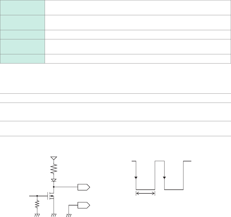
Output signal Open-drain output (with voltage output), active low
Output voltage
range
High level: 4.0 V to 5.0 V
Low level: 0 V to 0.5 V
Maximum input
voltage
50 V DC, 50 mA, 200 mW
GND
OUT1
OUT2
100
kΩ
10 kΩ
5 V
High
4.0 V to 5.0 V
Low
0 V to 0.5 V
Output period
213
External Input and Output
Trigger output (TRIG.OUT)
The instrument outputs the signal when it is triggered. You can use this signal to control multiple
instruments, achieving synchronous operation.
How to output the signal
1
Connect each of the TRIG OUT and GND terminals to an external signal-inputting device
with wires.
Refer to “2.3 Connecting the External Control Terminals” in Quick Start Manual.
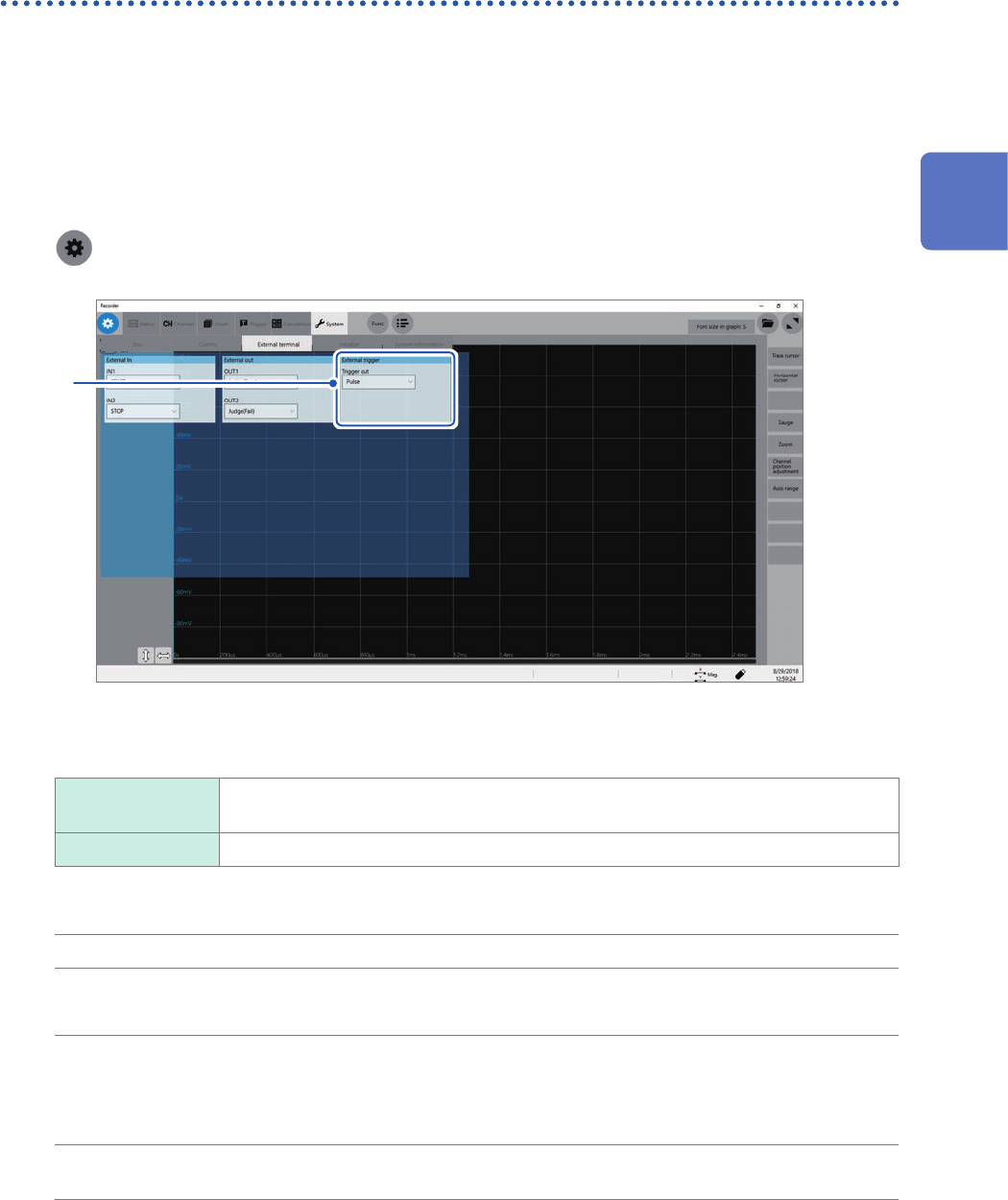
2
> [System] > [External terminal]
3
3
In the [External trigger] area, click the [Trigger out] box, and then from the list, choose a
signal output method.
Pulse
Outputs a low-level signal, and then switches it to the high level after the specied time
has elapsed.
Level at time Continuously outputs a low-level signal after triggered during the measurement.
When triggered, the instrument outputs a pulse wave, which switches from the high level (4.0 V to 5.0 V) to the
low level (0 V to 0.5 V).
Output signal Open-drain output (with voltage output), active low*
Output voltage range High level: 4.0 V to 5.0 V
Low level: 0 V to 0.5 V
Pulse width With the pulse
setting:
2 ms ±1 ms
When the level
setting:
(Sampling rate) × (Number of data points after trigger) or longer
Maximum input
voltage
50 V DC, 50 mA, 200 mW
*: The instrument is triggered when the signal voltage level switches from the high level to the low level.
12
Externally Controlling the Instrument