MR8740T_user_manual_eng_20191016H.pdf - 第221页
216 External Input and Output 4 Click [External trigger] . The setting dialog box will appear . (1) (2) (3) (1) Set [Ex ternal star t trigger ] to [On] . (2) Cl ic k th e box to the ri gh t of the [Ext ernal s tar t t ri…
215
External Input and Output
External trigger terminal (EXT.TRIG)
Externally inputting the trigger signal can trigger the instrument. You can use this signal to control
multiple instruments, achieving synchronous operation.
How to an input signal
1
Connect each of the EXT.TRIG and GND terminals to an external signal-outputting device
with wires.
Refer to “2.3 Connecting the External Control Terminals” in Quick Start Manual.
2
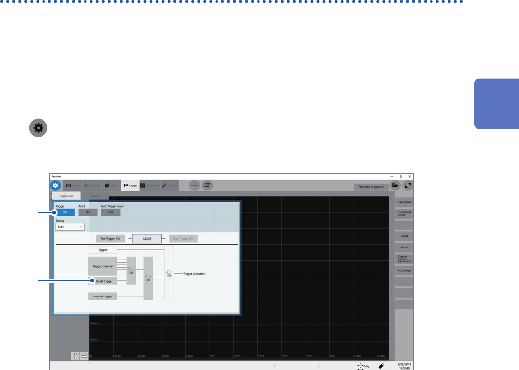
> [Trigger] > [Common]
3
Click the [Trigger] button to set it to [On].
3
4
12
Externally Controlling the Instrument
216
External Input and Output
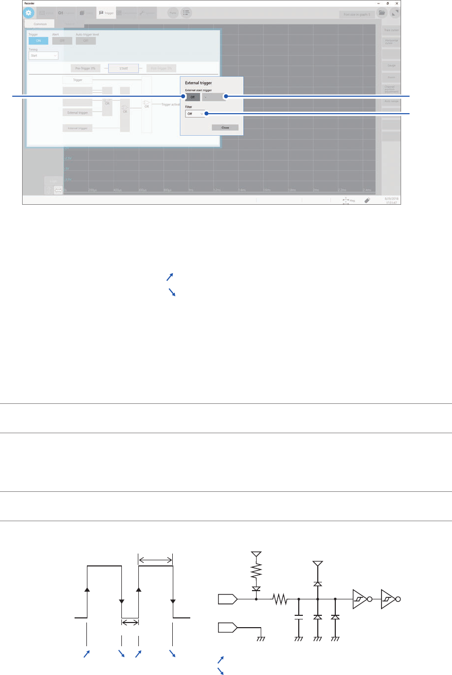
4
Click [External trigger].
The setting dialog box will appear.
(1)
(2)
(3)
(1) Set [External start trigger] to [On].
(2) Click the box to the right of the [External start trigger] box, and then from the list, choose
which direction to use for reception of the external trigger.
With the rising edge setting: [
]*
With the falling edge setting: [
]*
(3) Click the [Filter] box, and then choose a lter setting from the list.
5
Connect the EXT.TRIG terminal and GND, or input the pulse waves or rectangular waves to
the EXT.TRIG terminal. The signal shall have a high-level voltage of between 2.5 V and 10 V
and a low-level voltage of between 0 V and 0.8 V.
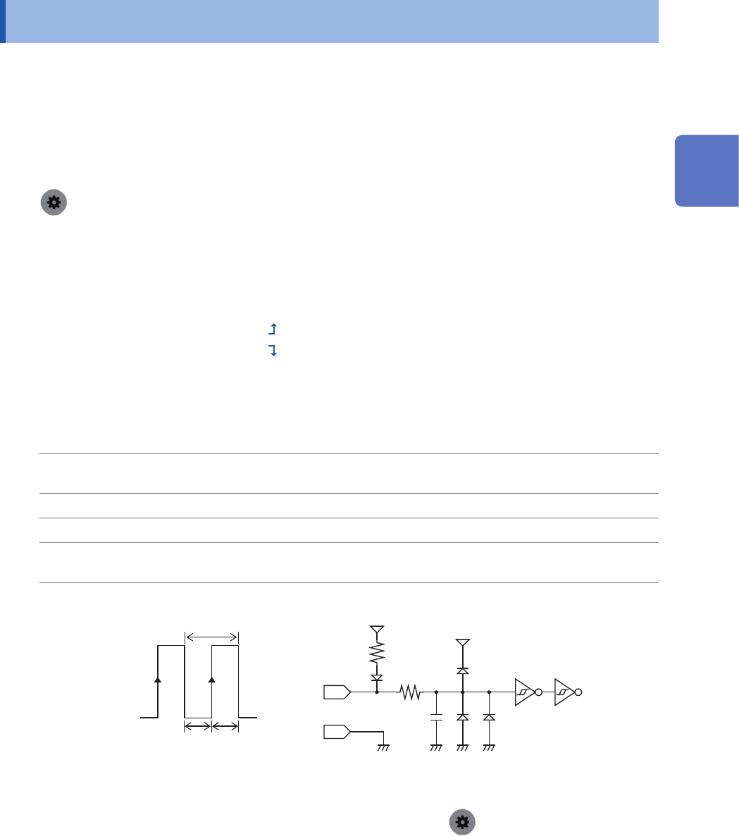
The instrument accepts the external trigger on the rising or falling edge of the input waveform.
Available voltage
range
High level: 2.5 V to 10 V; low level: 0 V to 0.8 V
Pulse width Whit the lter
disabled
High level: 1 ms or more; Low level: 2 μs or more
With the lter
enabled
High and low level: 2.5 ms or more
Maximum input
voltage
10 V DC
[ ]* [ ]*[ ]* [ ]*
[ ]*:
[ ]*:
5 V
EXT. TRIG
5 V
3 kΩ
9 kΩ
22 pF
GND
High
2.5 V to 10 V
Low
0 V to 0.8 V
With the rising edge setting
With the falling edge setting
*: When the trigger logical-condition is set to [AND], [High] or [Low] is displayed.
217
External Sampling (EXT.SMPL)
12.2 External Sampling (EXT.SMPL)
Externally inputting the signal can control the sampling rate.
How to an input signal
1
Connect each of the EXT.SMPL and GND terminals to an external signal-outputting device
with wires.
2
> [Status] > [Condition]
3
Click the [External sampling] button to set it to [On].
4
Click the box to the right of the [External sampling] box, and then from the list, choose
which direction to use for reception of the external sampling signal.
With the rising edge setting: [
]
With the rising edge setting: [
]
5
Input pulse waves or rectangular waves to the EXT.SMPL terminal. The signal shall have a
high-level voltage of between 2.5 V and 10 V and a low-level voltage of between 0 V and 0.8 V.
Available voltage
range
High level: 2.5 V to 10 V; low level: 0 V to 0.8 V
Pulse width High and low level: 50 ns or more
Response frequency 10 MHz or less
Maximum input
voltage
10 V DC
EXT. SMPL 600 Ω
10 pF
5 V
GND
3 kΩ
5 V
t
t
H
t
L
t
H
> 50 ns, t
L
> 50 ns, t > 100 ns
High
2.5 V to 10 V
Low
0 V to 0.8 V
• If a sampling signal with 5 MHz or more is inputted, trigger points are delayed by one sample.
• When Model 8968 High Resolution Unit is used, the anti-aliasing lter (
> [Channel] > [each Unit] >
[A.A.F.]) setting of [On] is invalid.
12
Externally Controlling the Instrument