MR8740T_user_manual_eng_20191016H.pdf - 第223页
218 External Sampling (EXT .SMPL)
217
External Sampling (EXT.SMPL)
12.2 External Sampling (EXT.SMPL)
Externally inputting the signal can control the sampling rate.
How to an input signal
1
Connect each of the EXT.SMPL and GND terminals to an external signal-outputting device
with wires.
2
> [Status] > [Condition]
3
Click the [External sampling] button to set it to [On].
4
Click the box to the right of the [External sampling] box, and then from the list, choose
which direction to use for reception of the external sampling signal.
With the rising edge setting: [
]
With the rising edge setting: [
]
5
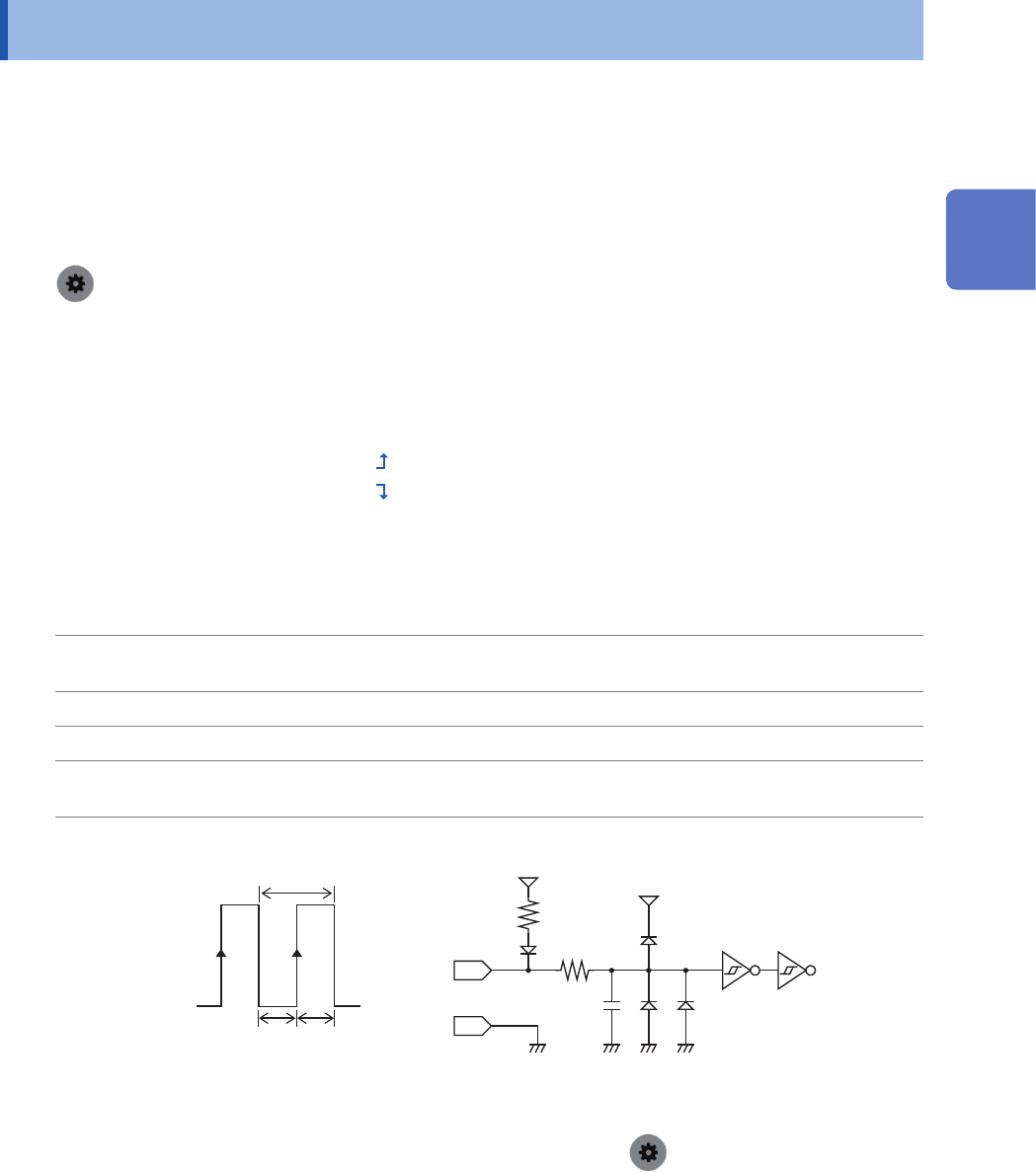
Input pulse waves or rectangular waves to the EXT.SMPL terminal. The signal shall have a
high-level voltage of between 2.5 V and 10 V and a low-level voltage of between 0 V and 0.8 V.
Available voltage
range
High level: 2.5 V to 10 V; low level: 0 V to 0.8 V
Pulse width High and low level: 50 ns or more
Response frequency 10 MHz or less
Maximum input
voltage
10 V DC
EXT. SMPL 600 Ω
10 pF
5 V
GND
3 kΩ
5 V
t
t
H
t
L
t
H
> 50 ns, t
L
> 50 ns, t > 100 ns
High
2.5 V to 10 V
Low
0 V to 0.8 V
• If a sampling signal with 5 MHz or more is inputted, trigger points are delayed by one sample.
• When Model 8968 High Resolution Unit is used, the anti-aliasing lter (
> [Channel] > [each Unit] >
[A.A.F.]) setting of [On] is invalid.
12
Externally Controlling the Instrument
218
External Sampling (EXT.SMPL)
219
13 Appendix
13
Appendix
13.1 Information for Reference Purposes
Waveform le size (values for reference purposes)
Waveform le size (for reference)
(MEM le size) = (Setting part size) + (Data part size)
(Setting part size) = 791040 + 512 × [(Number of analog channels) + 4 × (Number of logic channels) +
(Number of real-time calculation channels)]
(Data part size) = {2 × [(Number of analog channels other than Model MR8990 or U8991) + (Number of
logic modules)] + 4 × [(Number of channels of Models MR8990 and U8991) + (Number of
real-time calculation channels)]} × (Number of data sets)
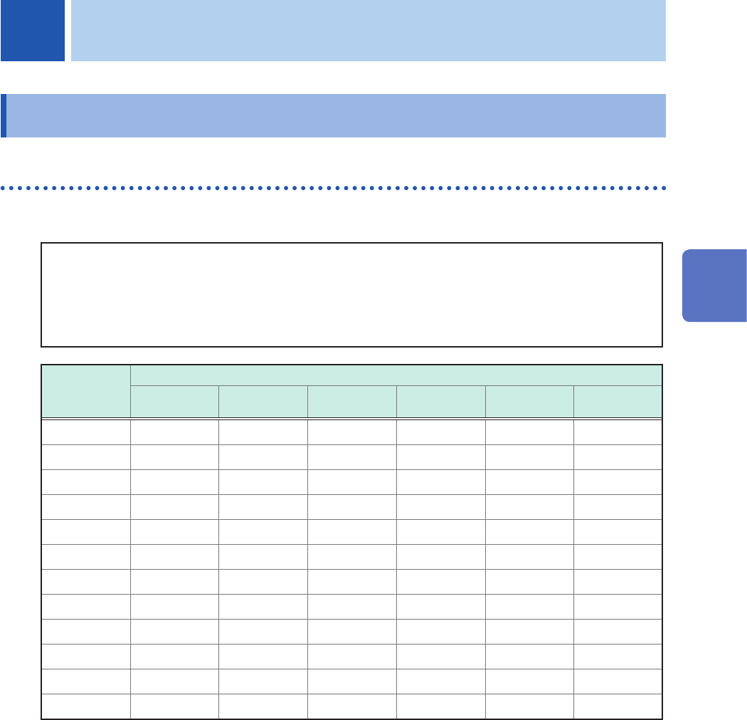
Recording
length
(Points)
Number of channels saved
4 8 16 32 54 108
2.5 k 815 KB 839 KB 887 KB 983 KB 1.1 MB 1.4 MB
5 k 835 KB 879 KB 967 KB 1.1 MB 1.4 M 2.0 MB
10 k 875 KB 959 KB 1.1 MB 1.5 MB 2.0 MB 3.0 MB
20 k 955 KB 1.1 MB 1.4 MB 2.1 MB 3.0 MB 5.2 MB
50 k 1.2 MB 1.6 MB 2.4 MB 4.0 MB 6.2 MB 11.7 MB
100 k 1.6 MB 2.4 MB 4.0 MB 7.2 MB 11.6 MB 22.5 MB
200 k 2.4 MB 4.0 MB 7.2 MB 13.6 MB 22.4 MB 44.1 MB
500 k 4.8 MB 8.8 MB 16.8 MB 32.8 MB 54.8 MB 108.9 MB
1 M 8.8 MB 16.8 MB 32.8 MB 64.8 MB 108.8 MB 216.9 MB
2 M 16.8 MB 32.8 MB 64.8 MB 128.8 MB 216.8 MB 432.9 MB
5 M 40.8 MB 80.8 MB 160.8 MB 320.8 MB 540.8 MB 1.1 GB
10 M 80.8 MB 160.8 MB 320.8 MB 640.8 MB 1.1 GB –
• These sizes, which can be used only as a reference, of text les are acquired when analog channels (other
than Model MR8990 or Model U8991) are used. Any number of logic channels on one module occupies one
channel; one analog channel (Model MR8990 and Model U8991) occupies two channels each.
• The instrument divides les with a size that exceeds 512 MB into multiple les of about 512 MB each to save
them.
13
Appendix