MR8740T_user_manual_eng_20191016H.pdf - 第56页
51 Conguring Measuring-Module-Specic Settings Conguring Model 8970 Freq Unit settings > [Channel] > [8970] 1 to 2 12 1 Click the [Mode] box, and then choose a measurement mode from the list. Frequency Measures…

50
Conguring Measuring-Module-Specic Settings
To execute auto-balance on the list screen
> [Channel] > > [Operate] > [Auto balance]
Executes auto-balance for all channels of the strain modules installed in the instrument.
In the following cases, execute auto-balance again.
• After changing the vertical axis (strain axis) range
• After replacing any modules
• After replacing the strain gauge converter
• After cycling the instrument
• After initializing the instrument
• When the ambient temperature has signicantly changed (the zero position may drift)
If auto-balance fails
Check the following items, and re-execute auto-balance.
• Is the strain gauge converter not subjected to any load?
(Make sure that the strain gauge converter is not subjected to vibration or any other loads.)
• Is the strain gauge converter properly connected measuring object?
• Is the measuring object not subjected to any load?
51
Conguring Measuring-Module-Specic Settings
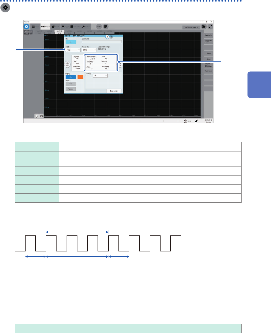
Conguring Model 8970 Freq Unit settings
> [Channel] > [8970]
1
to
2
12
1
Click the [Mode] box, and then choose a measurement mode from the list.
Frequency
Measures frequency of a waveform (in hertz [Hz]).
Rotation speed Measures the number of rotations of a measuring object (in rotations per minute [r/
min]).
Power frequency Measures power frequency uctuation (in hertz [Hz]).
Count Accumulates the number of input pulses.
Duty ratio Measures duty ratios of a waveform to be measured (in percent [%]).
Pulse width Measures pulse widths (in second [s]).
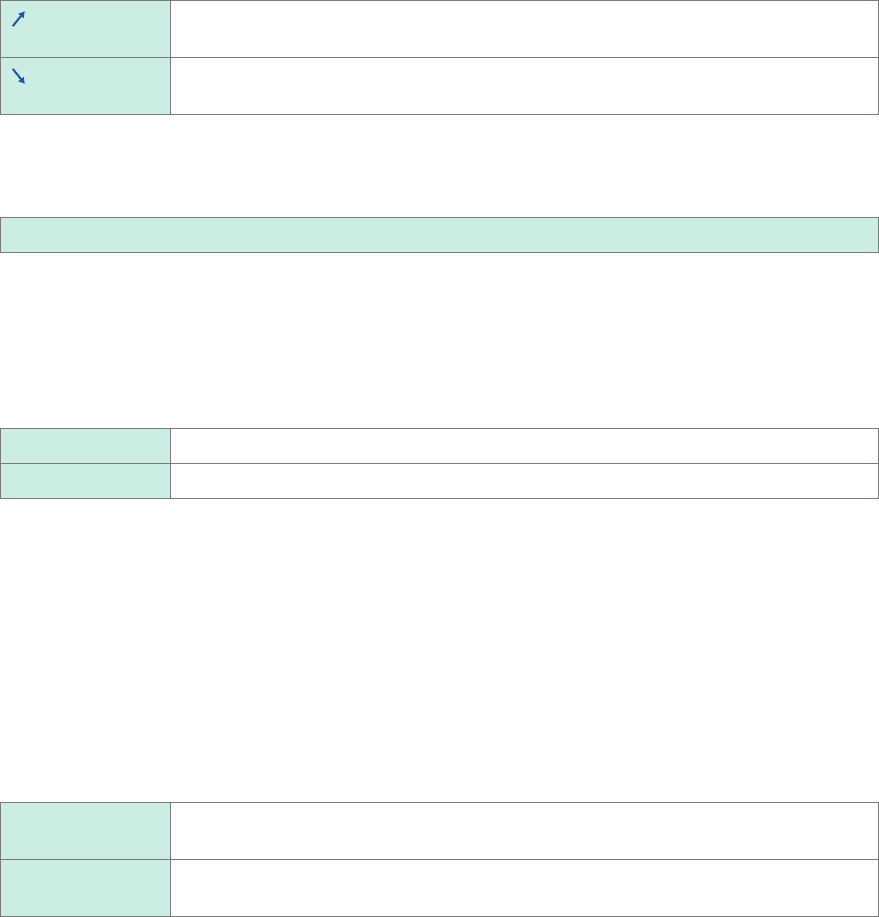
Pulses that rise during the dead time (during a calculation) cannot be measured (with a frequency of 25 kHz or
higher).
Ignored
Calculation (40 μs)Acquisition of
the waveform
Acquisition of
the waveform
2
Click the area that includes [Input voltage].
The setting dialog box appears.
3
Click the [Input voltage] box, and then choose an option for the maximum level of an input
signal from the list.
±10 V
, ±20 V, ±50 V, ±100 V, ±200 V, ±400 V
3
Advanced Functions
52
Conguring Measuring-Module-Specic Settings
4
Click the [Threshold] box, and then enter a threshold value.
• Measured values are acquired based on the following: the interval between the subsequent two points
when measured waveform exceeds (or falls below) the threshold value, and the number of times when the
waveform exceeds (or falls below) the threshold value.
• The upper and lower limits of the threshold value and the increment in the threshold value vary depending
on the input voltage setting.
To prevent measurement errors due to noise, a hysteresis width of about 3% of the input voltage is tolerated
for the threshold.
(When [Input voltage] is set to [±10 V], it stands at about ±0.3 V.)
Specify a threshold allowing for tolerance that exceeds the hysteresis width relative to a peak voltage.
5
Click the [Slope] box, and then from the list, choose a signal direction to be detected.
Detects a waveform when it exceeds the specied threshold value (in the positive
direction).
Detects a waveform when it falls below the specied threshold value (in the negative
direction).
6
Click the [Division], and then enter a pulse count used for calculating frequency.
1
to 4,096
Example: For an encoder that outputs 360 pulses per rotation, set [Division] at [360] to measure a frequency
each rotation. When [Division] is not used, set it at [1].
7
Click the [Timing] box, and then from the list, choose a condition used for starting a count.
Only when [Mode] is set to [Count], this setting is available.
Start
Clicking the start icon starts accumulating.
Trigger Starts a count when the instrument is triggered.
• When [Timing] is set to [Start], some internal processing time is required between the time when the start
icon is clicked and the start of a measurement. Thus, the count value is not zero at the start point.
• When the [Timing] is set to [Start], an input that exceeds the trigger level does not trigger the instrument
while the instrument is lling the pre-trigger memory. Furthermore, the time for internal processing at the
start and the trigger priority setting may not cause the instrument to trigger even when the input signal
exceeds the specied trigger level.
• The memory division may cause the last data of the previous block to remain in the top of the block.
8
Click the [Count over] box, and then from the list, choose an action to be performed when a
count number is saturated.
Only when [Mode] is set to [Count], this setting is available.
Hold
Counts pulses and stops counting when the pulse count reaches the upper limit (65535
for the 40 k range).
Undo Starts counting pulses and brings the count back to zero when the pulse count reaches
25 times of the range gure (50000 for the 40 k range).