IPC-SM-782A 表面安装设计和焊盘设计标准(带BGA).pdf - 第10页
6. High performance pr oducts consisting of ground-based and shipbound military products, high speed and high capacity computers, critical process controllers, and life supporting medical systems. Quality , reliability a…

Surface Mount Design and Land Pattern Standard
1.0 SCOPE
This document provides information on land pattern geom-
etries used for the surface attachment of electronic compo-
nents. The intent of the information presented herein is to
provide the appropriate size, shape and tolerance of surface
mount land patterns to insure sufficient area for the appro-
priate solder fillet, and also to allow for inspection and
testing of those solder joints.
1.1 Purpose
Although, in many instances, the land pat-
tern geometries can be slightly different based on the type
of soldering used to attach the electronic part, wherever
possible, land patterns are defined in such a manner that
they are transparent to the attachment process being used.
Designers should be able to use the information contained
herein to establish standard configurations not only for
manual designs but also for computer aided design sys-
tems. Whether parts are mounted on one or both sides of
the board, subjected to wave, reflow, or other type of sol-
dering, the land pattern and part dimensions should be opti-
mized to insure proper solder joint and inspection criteria.
Although patterns are standardized, since they are a part of
the printed board circuitry geometry, they are subject to the
producibility levels and tolerances associated with plating,
etching, or other conditions. The producibility aspects also
pertain to the use of solder mask and the registration
required between the solder mask and the conductor pat-
terns. (See paragraph 1.2.2).
1.2 Performance Classification
Three general end-
product classes have been established in associated IPC
standards and specifications to reflect progressive increases
in sophistication, functional performance requirements and
testing/inspection frequency. It should be recognized that
there may be an overlap of equipment between classes.
Design requirements determine class. Class definitions are
useful for identifying degrees of precision needed to meet
design/performance requirements of packaging and inter-
connecting structures, and establish communication media
between design and manufacture and disciplines.
The printed board user has the responsibility to determine
the class to which his product belongs. The contract shall
specify the performance class required and indicate any
exceptions to specific parameters, where appropriate. In the
event of conflict between the design requirements and the
classes defined herein, the former shall take precedence
and be reflected in the master drawing.
These classes are:
CLASS 1 General Electronic Products
Includes consumer products, some computer and computer
peripherals, as well as general military hardware suitable
for applications where cosmetic imperfections are not
important and the major requirement is function of the
completed printed board or printed board assembly.
CLASS 2 Dedicated Service Electronic Products
Includes communications equipment, sophisticated busi-
ness machines, instruments and military equipment where
high performance and extended life is required, and for
which uninterrupted service is desired but is not critical.
Certain cosmetic imperfections are allowed.
CLASS 3 High Reliability Electronic Products
Includes the equipment for commercial and military prod-
ucts where continued performance or performance on
demand is critical. Equipment downtime cannot be toler-
ated, and functionality is required for such applications as
life support items, or missile systems. Printed boards and
printed board assemblies in this class are suitable for appli-
cations where high levels of assurance are required and
service is essential.
The land patterns in this standard have the capability of
accommodating all three performance classifications.
1.2.1 End-Use Applications
In addition to the three per-
formance classifications, the Surface Mount Council has
established end use applications for electronic products.
These are:
1. Consumer products including games, toys, audio and
video electronics. In general, convenient size and
maximum functionality are important but product cost
is extremely important.
2. General purpose computers, as used in businesses and
personal applications. Compared to consumer prod-
ucts, customers expect longer life and more consistent
service.
3. Telecom products including telephone, switching sys-
tems, PBXs, and exchanges. These products are used
in applications expecting long service life and endur-
ing relatively harsh environments.
4. Commercial aircraft requiring small size, light weight
and high reliability.
5. Industrial products and passenger compartment auto-
motive applications. Size and function is a byword of
these products. Cost is very important, provided that
reducing product cost doesn’t forfeit the highest
achievable product quality, performance, and function.
December 1999 IPC-SM-782A
1
电子技术应用 www.ChinaAET.com

6. High performance products consisting of ground-based
and shipbound military products, high speed and high
capacity computers, critical process controllers, and
life supporting medical systems. Quality, reliability
and performance are paramount, closely followed by
size and function. Cost is optimized based on these
requirements but is less important.
7. Space products include all of the products above which
are built to meet harsh outer space conditions. This
implies high quality and performance over a wide
range of environmental and physical extremes.
8. Military avionics products built to meet demanding
mechanical and thermal changes. Size, weight, perfor-
mance and reliability are paramount.
9. Under the hood automotive electronics products
endure the harshest of all use environments. These
products face extreme temperatures and mechanical
variations. Adding to this is the pressure of achieving
the lowest cost and optimum manufacturability in high
volumes.
1.2.2 Producibility Levels
When appropriate this stan-
dard will provide three design complexity levels of fea-
tures, tolerances, measurements, assembly, testing of
completion or verification of the manufacturing process
that reflect progressive increases in sophistication of tool-
ing, materials or processing and, therefore progressive
increases in fabrication cost. These levels are:
Level A General Design Complexity—Preferred
Level B Moderate Design Complexity—Standard
Level C High Design Complexity—Reduced Produc-
ibility
Producibility levels also pertain to the assembly. The three
component mounting complexity levels which reflect pro-
gressive increases in sophistication of tooling, assembly
and joining techniques and therefore progressive increases
in cost are:
Level A simple assembly techniques used to describe
through the board component mounting;
Level B moderate assembly techniques used to
describe surface component mounting and
Level C complex assembly techniques used to
describe intermixing of through-the-board
and surface mounting on the same assembly.
Classification of complexity should not be confused with
the performance classification of end-item use described in
paragraph 1.2.
1.3 Assembly Types A type designation signifies further
sophistication describing whether components are mounted
on one or both sides of the packaging and interconnecting
structure. Type 1 defines an assembly that has components
mounted on only one side; type 2 is an assembly with
components on both sides. Type 2 is limited to only class
B or C assemblies.
Figure 1–1 shows the relationship of two types of assem-
blies.
The need to apply certain design concepts should depend
on the complexity and precision required to produce a par-
ticular land pattern or P&I structure. Any design class may
be applied to any of the end-product equipment categories;
therefore, a moderate complexity (Type 1B) would define
components mounted on one side (all surface mounted) and
when used in a Class 2 product (dedicated service electron-
ics) is referred to as Type 1B, Class 2. The product
described as a Type 1B, Class 2 might be used in any of the
end-use applications; the selection of class being dependent
on the requirements of the customers using the application.
1.4 Presentation
Dimensions and tolerances are
expressed in millimeters (mm) or microns (mn) as appro-
priate. When no unit of measurement is shown, the unit
shall be assumed to be ‘‘mm.’’ Reference information for
inch conversion is shown in the appendix.
1.5 Profile Tolerances
Profile tolerances are used in the
dimensioning system for determining the relationship
between component outlines and land pattern geometries.
The details are described in Section 3.3, and follow the
principles set forth in ANSI Y14.5. All dimensions are con-
sidered maximum or minimum material condition (depend-
ing on the features being analyzed), thus the profile toler-
ances are unilateral (one-direction—maximum to
minimum, or minimum to maximum) as opposed to bilat-
eral (plus or minus) from a nominal characteristic.
1.6 Land Pattern Determination
This document dis-
cusses two methods of providing information on land pat-
terns:
(1) exact details based on industry component specifica-
tions, board manufacturing and component placement
accuracy capabilities. These land patterns are regis-
tered to a specific component, and have a registered
land pattern number, see Table 3.5 and paragraph
3.3.3.4.
(2) equations that can be used to alter the given informa-
tion to achieve a more robust solder connection, when
used in particular situations where the equipment for
placement or attachment are more or less precise than
the assumptions made when determining the exact land
pattern details.
1.6.1 General Usage of SMT In general, a product is a
good candidate for SMT if it needs to be:
IPC-SM-782A December 1999
2
电子技术应用 www.ChinaAET.com
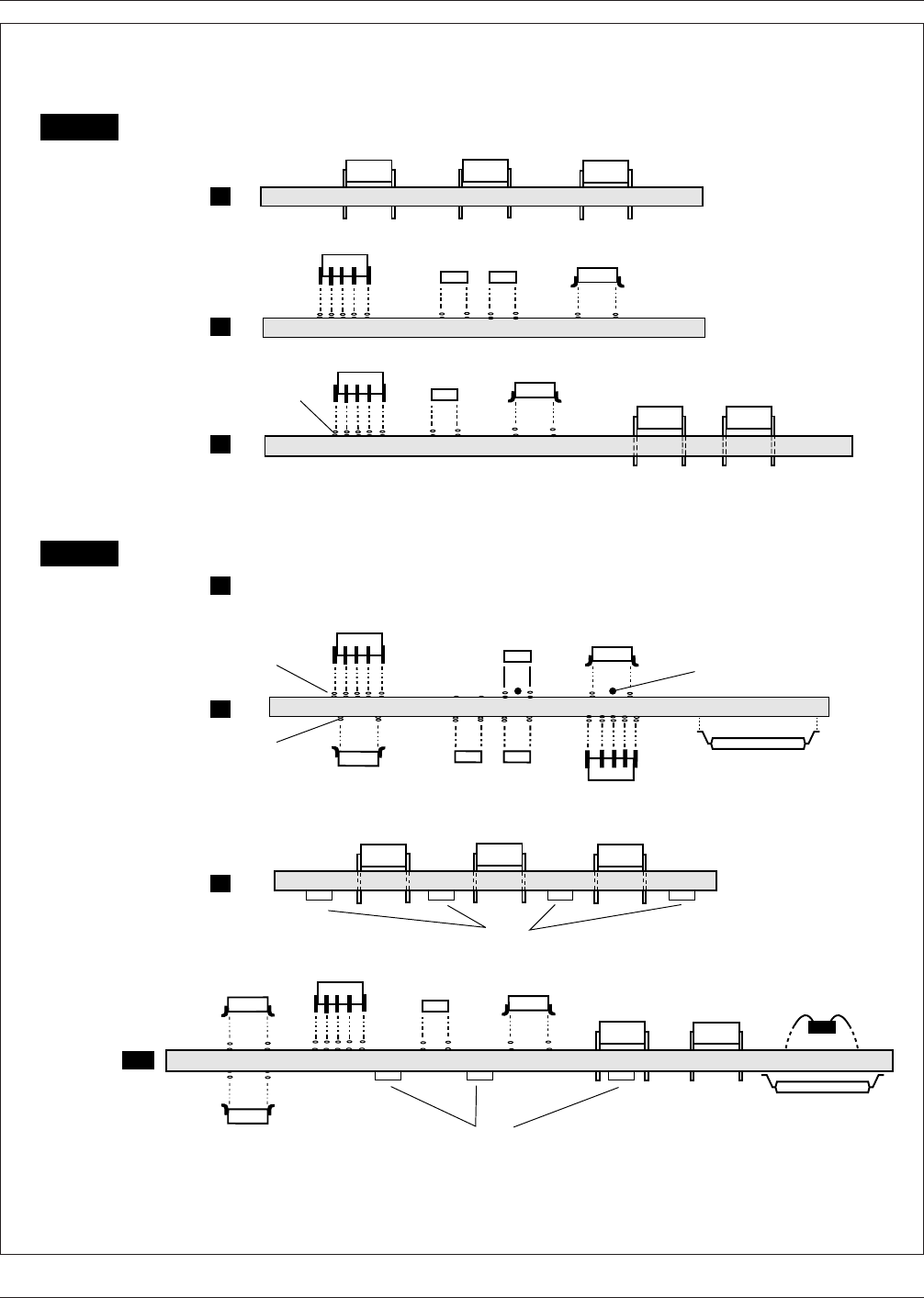
IPC-782-1-1
Figure 1–1 Electrical assembly types
PLCC
CHIP COMPONENT
SOIC
DIP
PLCC
CHIP
COMPONENT
SOIC
DIP
PLCC
CHIP COMPONENT
SOIC
PLCC
2-Sided Thru-hole (NOT RECOMMENDED)
SO
CHIP
COMPONENT
PLCC
CHIP
COMPONENT
CHIP
COMPONENT
SOIC
CHIP
COMPONENT
SOIC
DIP
SOLDER
PASTE
SOLDER
PASTE
SOIC
A
B
C
Through-hole
Simple
SMT
Simple
SMT/TH
Complex
Type 1
Type 2
B
C
CX
SMT
Complex
TH/SMT
Simple
SMT/TH
FPT/CMT
Complex
A
SOLDER
PASTE
Adhesive (Optional)
FPT
Simple
Wire bond or
tab IC chip
attachment
FPT PKG.
(selectively attached)
December 1999 IPC-SM-782A
3
电子技术应用 www.ChinaAET.com