IPC-SM-782A 表面安装设计和焊盘设计标准(带BGA).pdf - 第11页
IPC-782-1-1 Figure 1–1 Electrical assembly types PLCC CHIP COMPONENT SOIC DIP PLCC CHIP COMPONENT SOIC DIP PLCC CHIP COMPONENT SOIC PLCC 2-Sided Thru-hole (NOT RECOMMENDED) SO CHIP COMPONENT PLCC CHIP COMPONENT CHIP COMP…

6. High performance products consisting of ground-based
and shipbound military products, high speed and high
capacity computers, critical process controllers, and
life supporting medical systems. Quality, reliability
and performance are paramount, closely followed by
size and function. Cost is optimized based on these
requirements but is less important.
7. Space products include all of the products above which
are built to meet harsh outer space conditions. This
implies high quality and performance over a wide
range of environmental and physical extremes.
8. Military avionics products built to meet demanding
mechanical and thermal changes. Size, weight, perfor-
mance and reliability are paramount.
9. Under the hood automotive electronics products
endure the harshest of all use environments. These
products face extreme temperatures and mechanical
variations. Adding to this is the pressure of achieving
the lowest cost and optimum manufacturability in high
volumes.
1.2.2 Producibility Levels
When appropriate this stan-
dard will provide three design complexity levels of fea-
tures, tolerances, measurements, assembly, testing of
completion or verification of the manufacturing process
that reflect progressive increases in sophistication of tool-
ing, materials or processing and, therefore progressive
increases in fabrication cost. These levels are:
Level A General Design Complexity—Preferred
Level B Moderate Design Complexity—Standard
Level C High Design Complexity—Reduced Produc-
ibility
Producibility levels also pertain to the assembly. The three
component mounting complexity levels which reflect pro-
gressive increases in sophistication of tooling, assembly
and joining techniques and therefore progressive increases
in cost are:
Level A simple assembly techniques used to describe
through the board component mounting;
Level B moderate assembly techniques used to
describe surface component mounting and
Level C complex assembly techniques used to
describe intermixing of through-the-board
and surface mounting on the same assembly.
Classification of complexity should not be confused with
the performance classification of end-item use described in
paragraph 1.2.
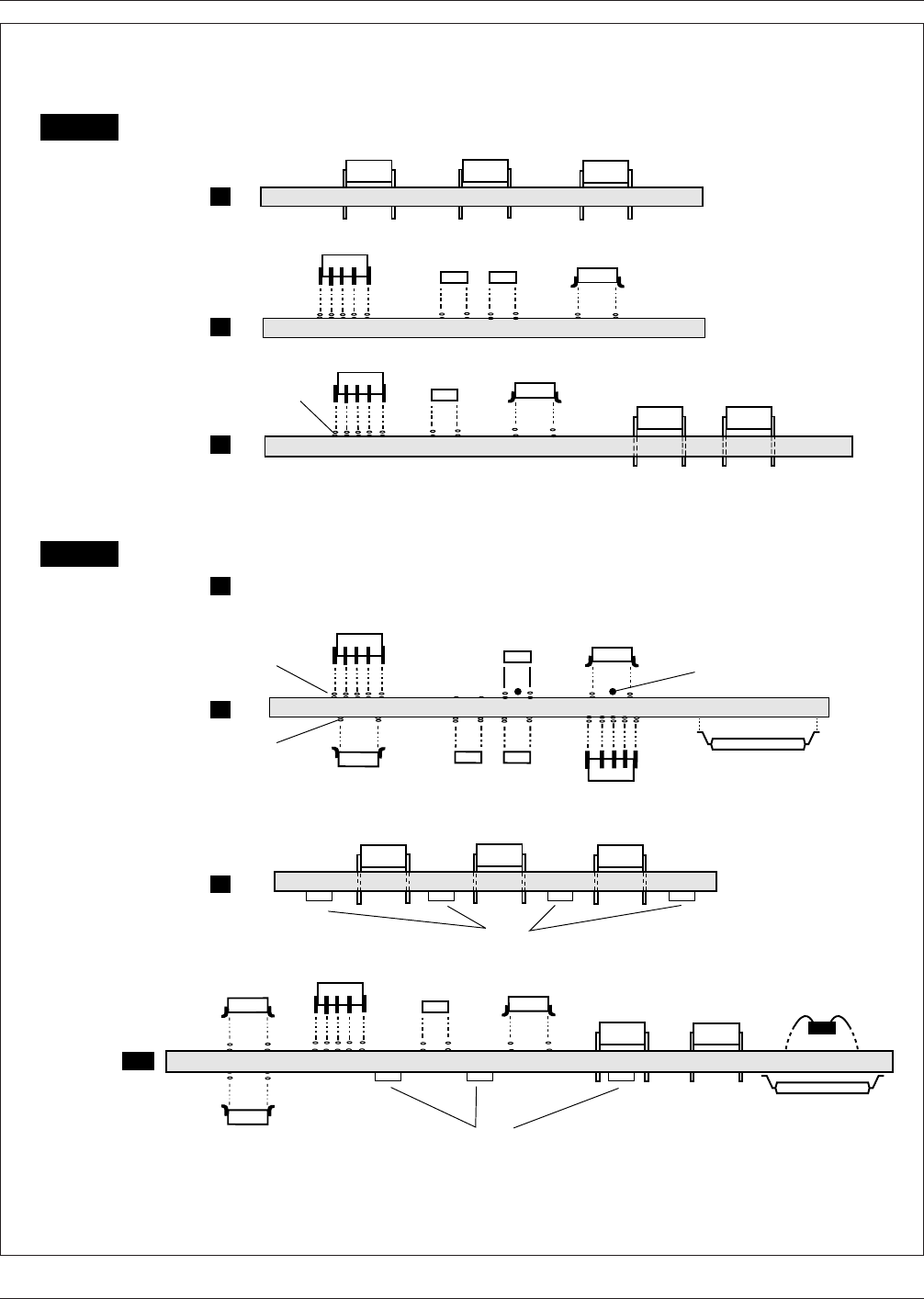
1.3 Assembly Types A type designation signifies further
sophistication describing whether components are mounted
on one or both sides of the packaging and interconnecting
structure. Type 1 defines an assembly that has components
mounted on only one side; type 2 is an assembly with
components on both sides. Type 2 is limited to only class
B or C assemblies.
Figure 1–1 shows the relationship of two types of assem-
blies.
The need to apply certain design concepts should depend
on the complexity and precision required to produce a par-
ticular land pattern or P&I structure. Any design class may
be applied to any of the end-product equipment categories;
therefore, a moderate complexity (Type 1B) would define
components mounted on one side (all surface mounted) and
when used in a Class 2 product (dedicated service electron-
ics) is referred to as Type 1B, Class 2. The product
described as a Type 1B, Class 2 might be used in any of the
end-use applications; the selection of class being dependent
on the requirements of the customers using the application.
1.4 Presentation
Dimensions and tolerances are
expressed in millimeters (mm) or microns (mn) as appro-
priate. When no unit of measurement is shown, the unit
shall be assumed to be ‘‘mm.’’ Reference information for
inch conversion is shown in the appendix.
1.5 Profile Tolerances
Profile tolerances are used in the
dimensioning system for determining the relationship
between component outlines and land pattern geometries.
The details are described in Section 3.3, and follow the
principles set forth in ANSI Y14.5. All dimensions are con-
sidered maximum or minimum material condition (depend-
ing on the features being analyzed), thus the profile toler-
ances are unilateral (one-direction—maximum to
minimum, or minimum to maximum) as opposed to bilat-
eral (plus or minus) from a nominal characteristic.
1.6 Land Pattern Determination
This document dis-
cusses two methods of providing information on land pat-
terns:
(1) exact details based on industry component specifica-
tions, board manufacturing and component placement
accuracy capabilities. These land patterns are regis-
tered to a specific component, and have a registered
land pattern number, see Table 3.5 and paragraph
3.3.3.4.
(2) equations that can be used to alter the given informa-
tion to achieve a more robust solder connection, when
used in particular situations where the equipment for
placement or attachment are more or less precise than
the assumptions made when determining the exact land
pattern details.
1.6.1 General Usage of SMT In general, a product is a
good candidate for SMT if it needs to be:
IPC-SM-782A December 1999
2
电子技术应用 www.ChinaAET.com
IPC-782-1-1
Figure 1–1 Electrical assembly types
PLCC
CHIP COMPONENT
SOIC
DIP
PLCC
CHIP
COMPONENT
SOIC
DIP
PLCC
CHIP COMPONENT
SOIC
PLCC
2-Sided Thru-hole (NOT RECOMMENDED)
SO
CHIP
COMPONENT
PLCC
CHIP
COMPONENT
CHIP
COMPONENT
SOIC
CHIP
COMPONENT
SOIC
DIP
SOLDER
PASTE
SOLDER
PASTE
SOIC
A
B
C
Through-hole
Simple
SMT
Simple
SMT/TH
Complex
Type 1
Type 2
B
C
CX
SMT
Complex
TH/SMT
Simple
SMT/TH
FPT/CMT
Complex
A
SOLDER
PASTE
Adhesive (Optional)
FPT
Simple
Wire bond or
tab IC chip
attachment
FPT PKG.
(selectively attached)
December 1999 IPC-SM-782A
3
电子技术应用 www.ChinaAET.com

• Small in size, real estate constrained
• Able to accommodate large amounts of memory
• Light in weight
• Able to accommodate several large, high lead count com-
plex ICs, such as ASICs and silicon arrays
• Able to function at high frequencies and speeds
• Able to transmit little or no noise, EMI and RFI resistant
• Able to be built in large volumes using automation
Currently, most SMT boards that have 50 or more compo-
nents use a combination of SMT and through-hole tech-
nologies. The mix is a function of component availability,
multiplicity of vendors, and cost. A mix of 80 percent SMT
and 20 percent through-hole parts is very common. How-
ever, the number of 100% SMT assemblies is increasing.
Fine Pitch Technology (FPT) involves a process change as
well as a packaging family, because the package to board
assembly steps are different than SMT. For example, sev-
eral commercially available FPT parts require lead excise
and forming prior to placement. They are encapsulated or
molded with plastic and delivered to users as a separate
packaged device, and these parts may be shipped with a
molded guard-ring or a slide carrier securing the leads in
place. The full encapsulated device will be used for direct
board mounting.
FPT packages are available under package names such as
PQFP (Plastic Quad Flat Pack), CQFP (Ceramic Quad Flat
Pack), QFP (Quad Flat Pack) and VSOIC (Very Small Out-
line Integrated Circuits).
2.0 APPLICABLE DOCUMENTS
The following documents, of the issue currently in effect
form a part of this document to the extend specified herein.
Other documents listed are for reference purposes to assist
the user.
2.1 IPC
1
IPC-A-48 Surface Mount Land Pattern Artwork (Mantech)
IPC-A-49
Surface Mount Land Pattern Artwork (IPC-SM-
782A)
IPC-T-50 Terms and Definitions
IPC-SC-60
Post Solder Solvent Cleaning Handbook
IPC-AC-62
Post Solder Aqueous Cleaning Handbook
IPC-2221
Generic Standard on Printed Board Design
IPC-6012
Qualification and Performance Standard for
Rigid Printed Boards
IPC-D-330
Printed Wiring Design Guide
IPC-A-610
Acceptability of Printed Board Assemblies
IPC-7711
Rework of Electronic Assemblies
IPC-SM-780
Guidelines for Component Packaging and
Interconnection with Emphasis on Surface Mounting
IPC-SM-784
Guidelines for Chip-on-Board Technology
Implementation
IPC-SM-785
Guidelines for Accelerated Reliability Testing
of Surface Mount Solder Attachments
IPC-SM-786
Recommended Procedures for Handling of
Moisture Sensitive Plastic IC Packages
IPC-AJ-820
Assembly and Joining Handbook
IPC-CC-830
Electrical Insulating Compounds for Printed
Board Assemblies
IPC-SM-840
Qualification and Performance of Permanent
Polymer Coating (Solder Mask) for Printed Boards
IPC-1902/IEC 60097
Grid System for Printed Circuits
2.2 Electronic Industries Association
2
IS-30
Surface Mount Resistors
JEDEC-95
JEDEC Registered and Standard Outlines for
Solid State Products
EIA-PDP-100
Registered and Standard Mechanical Out-
lines for Electronic Parts
RS-198
Ceramic Dielectric Capacitors
RS-228
Fixed Electrolytic Tantalum Capacitors
RS-367
Dimensional and Electrical Characteristics Defin-
ing Receiver Type Sockets
RS-376
Fixed Film Dielectric Capacitors in Metallic and
Non- Metallic Cases for D.C. Application
RS-415
Dimensional and Electrical Characteristic Defin-
ing Dual-In-Line-Type Sockets
RS-428
Type Designation System for Microelectronic
Devices
1. IPC, 2215 Sanders Road, Northbrook, IL 60062-6135
2. Electronic Industries Association, 2001 Eye Street N.W., Washington, DC 20006
IPC-SM-782A December 1999
4
电子技术应用 www.ChinaAET.com