IPC-SM-782A 表面安装设计和焊盘设计标准(带BGA).pdf - 第165页
RLP No. Component Identifier Z1 (mm) G1 (mm) Z2 (mm) G2 (mm) X (mm) Y (mm) C1 (mm) D1 (mm) C2 (mm) D2 (mm) E (mm) Placement Grid (No. of Grid Elements) ref ref ref ref ref ref 710A QFP 14X20-80 18.00 14.40 24.00 20.40 0.5…
Component Identifier
L (mm) S1 (mm) L2 (mm) S2 (mm) W (mm) T (mm)
P
(mm)
H
(mm)
A
(mm)
B
(mm)
Pin
Count,
Short
Side
Pin
Count,
Long
Sidemin max min max min max min max min max min max basic max ref ref
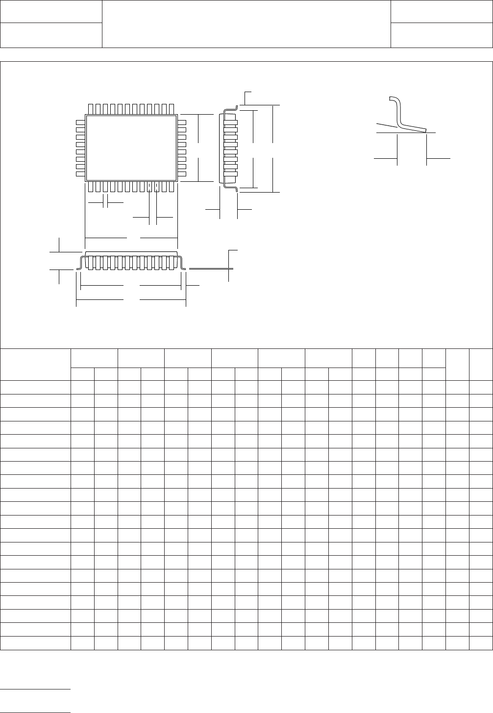
QFP-14x20-80 16.95 17.45 14.85 15.55 22.95 23.45 20.85 21.55 0.30 0.45 0.70 1.05 0.80 2.45 14.00 20.00 16 24
QFP-14x20-100 16.95 17.45 14.85 15.55 22.95 23.45 20.85 21.55 0.22 0.38 0.70 1.05 0.65 2.45 14.00 20.00 20 30
SQFP-14x20-120 15.80 16.20 14.20 14.89 21.80 22.20 20.20 20.89 0.10 0.30 0.40 0.80 0.50 2.20 14.00 20.00 24 36
SQFP-14x20-128 15.80 16.20 14.20 14.89 21.80 22.20 20.20 20.89 0.10 0.30 0.40 0.80 0.50 2.20 14.00 20.00 26 38
SQFP-14x20-152 15.80 16.20 14.20 14.89 21.80 22.20 20.20 20.89 0.05 0.22 0.40 0.80 0.40 2.20 14.00 20.00 30 46
SQFP-14x20-160 15.80 16.20 14.20 14.89 21.80 22.20 20.20 20.89 0.05 0.22 0.40 0.80 0.40 2.20 14.00 20.00 32 48
SQFP-14x20-208 15.80 16.20 14.20 14.89 21.80 22.20 20.20 20.89 0.05 0.15 0.40 0.80 0.30 2.20 14.00 20.00 42 62
SQFP-14x20-216 15.80 16.20 14.20 14.89 21.80 22.20 20.20 20.89 0.05 0.15 0.40 0.80 0.30 2.20 14.00 20.00 44 64
SQFP-20x28-176 21.80 22.20 20.20 20.89 29.80 30.20 28.20 28.89 0.10 0.30 0.40 0.80 0.50 3.75 20.00 28.00 36 52
SQFP-20x28-184 21.80 22.20 20.20 20.89 29.80 30.20 28.20 28.89 0.10 0.30 0.40 0.80 0.50 3.75 20.00 28.00 38 54
SQFP-20x28-224 21.80 22.20 20.20 20.89 29.80 30.20 28.20 28.89 0.05 0.22 0.40 0.80 0.40 3.75 20.00 28.00 46 66
SQFP-20x28-232 21.80 22.20 20.20 20.89 29.80 30.20 28.20 28.89 0.05 0.22 0.40 0.80 0.40 3.75 20.00 28.00 48 68
SQFP-20x28-300 21.80 22.20 20.20 20.89 29.80 30.20 28.20 28.89 0.05 0.15 0.40 0.80 0.30 3.75 20.00 28.00 62 88
SQFP-20x28-308 21.80 22.20 20.20 20.89 29.80 30.20 28.20 28.89 0.05 0.15 0.40 0.80 0.30 3.75 20.00 28.00 64 90
SQFP-28x40-256 29.80 30.20 28.20 28.89 41.80 42.20 40.20 40.89 0.10 0.30 0.40 0.80 0.50 4.20 28.00 28.00 52 76
SQFP-28x40-264 29.80 30.20 28.20 28.89 41.80 42.20 40.20 40.89 0.10 0.30 0.40 0.80 0.50 4.20 28.00 40.00 54 78
SQFP-28x40-324 29.80 30.20 28.20 28.89 41.80 42.20 40.20 40.89 0.05 0.22 0.40 0.80 0.40 4.20 28.00 40.00 66 96
SQFP-28x40-332 29.80 30.20 28.20 28.89 41.80 42.20 40.20 40.89 0.05 0.22 0.40 0.80 0.40 4.20 28.00 40.00 68 98
SQFP-28x40-432 29.80 30.20 28.20 28.89 41.80 42.20 40.20 40.89 0.05 0.15 0.40 0.80 0.30 4.20 28.00 40.00 88 128
SQFP-28x40-440 29.80 30.20 28.20 28.89 41.80 42.20 40.20 40.89 0.05 0.15 0.40 0.80 0.30 4.20 28.00 40.00 90 130
Figure 2b SQFP/QFP (Rectangular) component dimensions
~ 10°
T
▼
▼
▼
▼
▼
▼
▼
▼
W
B
P
▼
▼
A S1
▼
▼
▼
▼
H
▼
T
L1
▼
▼
▼
▼
▼
▼
▼
▼
▼
H
S2
L2
T
▼
▼
~ 0.25
IPC-782-11-3-2b
IPC-SM-782
Subject
SQFP/QFP (Rectangular)
Date
5/96
Section
11.3
Revision
A
Page4of6
电子技术应用 www.ChinaAET.com
RLP
No. Component Identifier
Z1
(mm)
G1
(mm)
Z2
(mm)
G2
(mm) X (mm)
Y (mm)
C1
(mm)
D1
(mm)
C2
(mm)
D2
(mm) E (mm)
Placement Grid
(No. of Grid
Elements)ref ref ref ref ref ref
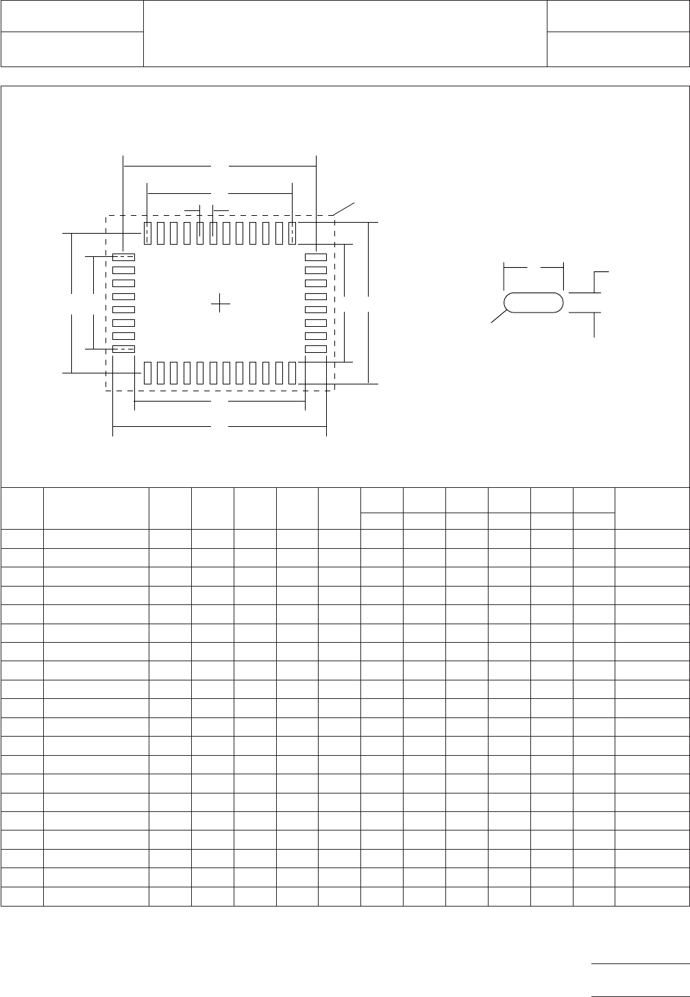
710A QFP 14X20-80 18.00 14.40 24.00 20.40 0.50 1.80 16.20 12.00 22.20 18.40 0.80 38x50
711A QFP 14X20-100 18.00 14.40 24.00 20.40 0.40 1.80 16.20 12.35 22.20 18.85 0.65 38x50
712A SQFP 14X20-120 16.80 13.60 22.80 19.60 0.30 1.60 15.20 11.50 21.20 17.50 0.50 36x48
713A SQFP 14X20-128 16.80 13.60 22.80 19.60 0.30 1.60 15.20 12.50 21.20 18.50 0.50 36x48
714A SQFP 14X20-152 16.80 13.60 22.80 19.60 0.25 1.60 15.20 11.60 21.20 18.00 0.40 36x48
715A SQFP 14X20-160 16.80 13.60 22.80 19.60 0.25 1.60 15.20 12.40 21.20 18.80 0.40 36x48
716A SQFP 14X20-208 16.80 13.60 22.80 19.60 0.17 1.60 15.20 12.30 21.20 18.30 0.30 36x48
717A SQFP 14X20-216 16.80 13.60 22.80 19.60 0.17 1.60 15.20 12.90 21.20 18.90 0.30 36x48
720A SQFP 20X28-176 22.80 19.60 30.80 27.60 0.30 1.60 21.20 17.50 29.20 25.50 0.50 48x66
721A SQFP 20X28-184 22.80 19.60 30.80 27.60 0.30 1.60 21.20 18.50 29.20 26.50 0.50 48x66
722A SQFP 20X28-224 22.80 19.60 30.80 27.60 0.25 1.60 21.20 18.00 29.20 26.00 0.40 48x66
723A SQFP 20X28-232 22.80 19.60 30.80 27.60 0.25 1.60 21.20 18.80 29.20 26.80 0.40 48x66
724A SQFP 20X28-300 22.80 19.60 30.80 27.60 0.17 1.60 21.20 18.30 29.20 26.10 0.30 48x66
725A SQFP 20X28-308 22.80 19.60 30.80 27.60 0.17 1.60 21.20 18.90 29.20 26.70 0.30 48x66
730A SQFP 28X40-256 30.80 27.60 42.80 39.60 0.30 1.60 29.20 25.50 41.20 37.50 0.50 66x88
731A SQFP 28X40-264 30.80 27.60 42.80 39.60 0.30 1.60 29.20 26.50 41.20 38.50 0.50 66x88
732A SQFP 28X40-324 30.80 27.60 42.80 39.60 0.25 1.60 29.20 26.00 41.20 38.00 0.40 66x88
733A SQFP 28X40-332 30.80 27.60 42.80 39.60 0.25 1.60 29.20 26.80 41.20 38.80 0.40 66x88
734A SQFP 28X40-432 30.80 27.60 42.80 39.60 0.17 1.60 29.20 26.10 41.20 38.10 0.30 66x88
735A SQFP 28X40-440 30.80 27.60 42.80 39.60 0.17 1.60 29.20 26.70 41.20 38.70 0.30 66x88
Figure 3b SQFP/QFP (Rectangular) land pattern dimensions
Y
X
Full radius
optional
▼
▼
▼
▼
▼
Z2
G2
▼
▼
▼
▼
E
▼
▼
C2
▼
▼
C1
G1 Z1
▼
▼
▼
▼
▼
▼
▼
Grid
placement courtyard
D2
▼
▼
D1
▼
▼
IPC-782-11-3-3b
IPC-SM-782
Subject
SQFP/QFP (Rectangular)
Date
5/96
Section
11.3
Revision
A
Page5of6
电子技术应用 www.ChinaAET.com
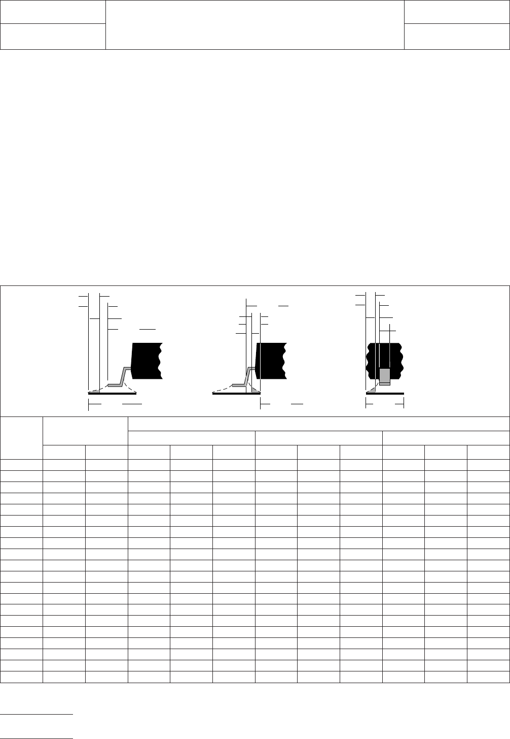
6.0 TOLERANCE AND SOLDER JOINT ANALYSIS
Figure 4 provides an analysis of tolerance assumptions and
resultant solder joints based on the land pattern dimensions
shown in Figure 3. Tolerances for the component dimensions,
the land pattern dimensions (fabrication tolerances on the
interconnecting substrate), and the component placement
equipment accuracy are all taken into consideration.
Figure 4 provides the solder joint minimums for toe, heel, and
side fillets, as discussed in Section 3.3. The tolerances are
addressed in a statistical mode, and assume even distribution
of the tolerances for component, fabrication, and placement
accuracy.
Individual tolerances for fabrication (‘‘F’’) and component
placement equipment accuracy (‘‘P’’) are assumed to be as
given in the table. These numbers may be modified based on
user equipment capability or fabrication criteria. Component
tolerance ranges (C
L
,C
S
, and C
W
) are derived by subtracting
minimum from maximum dimensions given in Figure 2. The
user may also modify these numbers, based on experience
with their suppliers. Modification of tolerances may result in
alternate land patterns (patterns with dimensions other than
the IPC registered land pattern dimensions).
The dimensions for minimum solder fillets at the toe, heel, or
side (J
T
,J
H
,J
S
) have been determined based on industry
empirical knowledge and reliability testing. Solder joint
strength is greatly determined by solder volume. An observ-
able solder fillet is necessary for evidence of proper wetting.
Thus, the values in the table usually provide for a positive sol-
der fillet. Nevertheless, the user may increase or decrease the
minimum value based on process capability.
RLP No.
Tolerance
Assumptions (mm)
Solder Joint (Sides 1 and 2)
Toe (mm) Heel (mm) Side (mm)
FPC
L
J
T
min J
T
max C
S
J
H
min J
H
max C
W
J
S
min J
S
max
680/681A 0.10 0.10 0.49 0.29 0.50 0.75 0.29 0.65 0.35 -0.02 0.10
682/683A 0.10 0.10 0.49 0.29 0.50 0.75 0.29 0.65 0.33 -0.01 0.10
684/685A 0.10 0.10 0.49 0.29 0.50 0.75 0.29 0.65 0.30 -0.03 0.06
690/691A 0.10 0.10 0.49 0.29 0.50 0.75 0.29 0.65 0.35 -0.02 0.10
692/693A 0.10 0.10 0.49 0.29 0.50 0.75 0.29 0.65 0.33 -0.01 0.10
694/695A 0.10 0.10 0.49 0.29 0.50 0.75 0.29 0.65 0.30 -0.03 0.06
700/701A 0.10 0.10 0.49 0.29 0.50 0.75 0.29 0.65 0.35 -0.02 0.10
702/703A 0.10 0.10 0.49 0.29 0.50 0.75 0.29 0.65 0.33 -0.01 0.10
704/705A 0.10 0.10 0.49 0.29 0.50 0.75 0.29 0.65 0.30 -0.03 0.06
710A 0.10 0.10 0.57 0.27 0.53 0.76 0.22 0.58 0.32 -0.00 0.10
711A 0.10 0.10 0.57 0.27 0.53 0.76 0.22 0.58 0.33 -0.02 0.09
712/713A 0.10 0.10 0.49 0.29 0.50 0.75 0.29 0.65 0.35 -0.02 0.10
714/715A 0.10 0.10 0.49 0.29 0.50 0.75 0.29 0.65 0.33 -0.01 0.10
716/717A 0.10 0.10 0.49 0.29 0.50 0.75 0.29 0.65 0.30 -0.03 0.06
720/721A 0.10 0.10 0.49 0.29 0.50 0.75 0.29 0.65 0.35 -0.02 0.10
722/723A 0.10 0.10 0.49 0.29 0.50 0.75 0.29 0.65 0.33 -0.01 0.10
724/725A 0.10 0.10 0.49 0.29 0.50 0.75 0.29 0.65 0.30 -0.03 0.06
730/731A 0.10 0.10 0.49 0.29 0.50 0.75 0.29 0.65 0.35 -0.02 0.10
732/733A 0.10 0.10 0.49 0.29 0.50 0.75 0.29 0.65 0.33 -0.01 0.10
734/735A 0.10 0.10 0.49 0.29 0.50 0.75 0.29 0.65 0.30 -0.03 0.06
Figure 4 Tolerance and solder joint analysis
Zmax
Lmin
▼
▼
▼
▼
1
/2 T
T
J
T
min
Smax
J
H
min
1
/2 T
H
Xmax
▼
▼
Toe Fillet
▼
▼
▼
Heel Fillet
Side Fillet
▼
▼
▼
▼
▼
J
T
max
J
H
max
J
S
min
▼
▼
▼
▼
▼
▼
▼
▼
▼
▼
▼
▼
▼
▼
▼
Gmin
▼
1
/2 T
S
J
S
max
▼
▼
▼
Wmin
▼
IPC-782-11-3-4
IPC-SM-782
Subject
SQFP/QFP (Rectangular)
Date
5/96
Section
11.3
Revision
A
Page6of6
电子技术应用 www.ChinaAET.com