IPC-SM-782A 表面安装设计和焊盘设计标准(带BGA).pdf - 第212页
4.0 COMPONENT DIMENSIONS Figures 1a-1b provides the component dimensions for square PBGAs. Component Contact Array ABCD W PH F o r G Identifier Rows x Cols. max max max max nom. basic max nom. PBGA 7x7 FE36 6x6 7.00 7.00 …

1.0 SCOPE
This subsection provides the component and land pattern
dimensions for square 1.0 mm pitch Plastic Ball Grid Arrays
(PBGA).
2.0 APPLICABLE DOCUMENTS
See Section 14.0 for documents applicable to the subsection.
3.0 COMPONENT DESCRIPTION
These components are all on 1.0 mm pitch. They are available
in a wide variety of body sizes. The data supplied in the detail
and table reflect a full matrix. Specific contact and depopula-
tion and pin assignment must be furnished by the device
manufacturer (see Section 14.0 for more information on
depopulation methods).
IPC-SM-782
Surface Mount Design
and Land Pattern Standard
Date
4/99
Section
14.1.3
Revision
—
Subject
1.0 mm Pitch PBGA
JEDEC MO-151
Page1of6
电子技术应用 www.ChinaAET.com
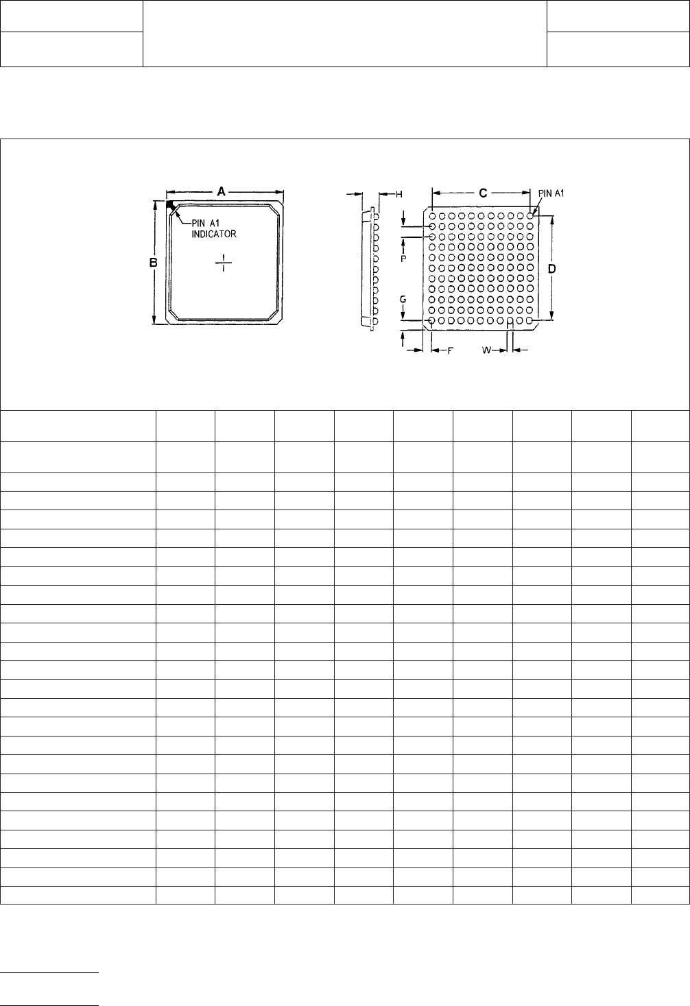
4.0 COMPONENT DIMENSIONS
Figures 1a-1b provides the component dimensions for square PBGAs.
Component
Contact
Array ABCDWPHForG
Identifier
Rows x
Cols. max max max max nom. basic max nom.
PBGA 7x7 FE36 6x6 7.00 7.00 5.00 5.00 0.60 1.00 3.50 1.00
PBGA 7x7 FO25 5x5 7.00 7.00 4.00 4.00 0.60 1.00 3.50 1.50
PBGA 8x8 F049 7x7 8.00 8.00 6.00 6.00 0.60 1.00 3.50 1.00
PBGA 8x8 FE36 6x6 8.00 8.00 5.00 5.00 0.60 1.00 3.50 1.50
PBGA 9x9 FE64 8x8 9.00 9.00 7.00 7.00 0.60 1.00 3.50 1.00
PBGA 9x9 FO49 7x7 9.00 9.00 6.00 6.00 0.60 1.00 3.50 1.50
PBGA 10x10 FO81 9x9 10.00 10.00 8.00 8.00 0.60 1.00 3.50 1.00
PBGA 10x10 FE64 8x8 10.00 10.00 7.00 7.00 0.60 1.00 3.50 1.50
PBGA 11x11 FE100 10x10 11.00 11.00 9.00 9.00 0.60 1.00 3.50 1.00
PBGA 11x11 FO81 9x9 11.00 11.00 8.00 8.00 0.60 1.00 3.50 1.50
PBGA 12x12 FO121 11x11 12.00 12.00 10.00 10.00 0.60 1.00 3.50 1.00
PBGA 12x12 FE100 10x10 12.00 12.00 9.00 9.00 0.60 1.00 3.50 1.50
PBGA 13x13 FE144 12x12 13.00 13.00 11.00 11.00 0.60 1.00 3.50 1.00
PBGA 13x13 FO121 11x11 13.00 13.00 10.00 10.00 0.60 1.00 3.50 1.50
PBGA 14x14 FO169 13x13 14.00 14.00 12.00 12.00 0.60 1.00 3.50 1.00
PBGA 14x14 FE144 12x12 14.00 14.00 11.00 11.00 0.60 1.00 3.50 1.50
PBGA 15x15 FE196 14x14 15.00 15.00 13.00 13.00 0.60 1.00 3.50 1.00
PBGA 15x15 FO169 13x13 15.00 15.00 12.00 12.00 0.60 1.00 3.50 1.50
PBGA 17x17 FE256 16x16 17.00 17.00 15.00 15.00 0.60 1.00 3.50 1.00
PGBA 17x17 FO225 15x15 17.00 17.00 14.00 14.00 0.60 1.00 3.50 1.50
PBGA 19X19 FE324 18X18 19.00 19.00 17.00 17.00 0.60 1.00 3.50 1.00
PBGA 19x19 FO289 17x17 19.00 19.00 16.00 16.00 0.60 1.00 3.50 1.50
PBGA 21X21 FE400 20X20 21.00 21.00 19.00 19.00 0.60 1.00 3.50 1.00
FE = Full Even Matrix
FO = Full Odd Matrix
Figure 1a PBGA component dimensions
IPC-SM-782
Subject
1.0 mm Pitch PBGA JEDEC MO-151
Date
4/99
Section
14.1.3
Revision
—
Page2of6
电子技术应用 www.ChinaAET.com
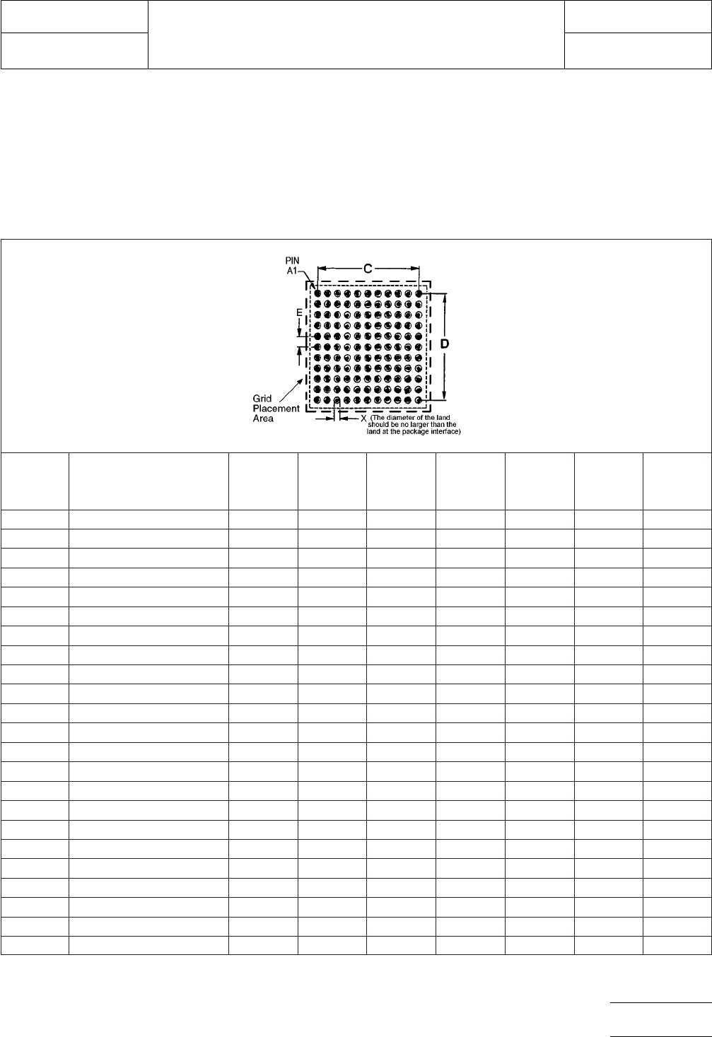
5.0 LAND PATTERN DIMENSIONS
Figures 2a-2b provide the land pattern dimensions for square
PBGA components. These numbers represent industry con-
sensus on the best dimensions based on empirical knowledge
of fabricated land patterns.
Note: The data supplied in the detail and table reflect a full
matrix. Specific contact and depopulation and pin assignment
must be furnished by the device manufacturer.
The dotted line in Figures 2a-2b shows the grid placement
courtyard which is the area required to place land patterns
and their respective components in adjacent proximity without
interference or shorting. Numbers in the table represent the
number of grid elements (each element is 0.5 by 0.5 mm) in
accordance with the international grid detailed in IEC publica-
tion 97.
RLP Component Identifier
Contact
Array
Rows x
Cols.
Max.
Contact
Count C D X E
Placement
Grid
900 PBGA 7x7 FE36 6x6 36 5.00 5.00 0.50 1.00 16X16
901 PBGA 7x7 FO25 5x5 25 4.00 4.00 0.50 1.00 16X16
902 PBGA 8x8 F049 7x7 49 6.00 6.00 0.50 1.00 18X18
903 PBGA 8x8 FE36 6x6 36 5.00 5.00 0.50 1.00 18X18
904 PBGA 9x9 FE64 8x8 64 7.00 7.00 0.50 1.00 20X20
905 PBGA 9x9 FO49 7x7 49 6.00 6.00 0.50 1.00 20X20
906 PBGA 10x10 FO81 9x9 81 8.00 8.00 0.50 1.00 22X22
907 PBGA 10x10 FE64 8x8 64 7.00 7.00 0.50 1.00 22X22
908 PBGA 11x11 FE100 10x10 100 9.00 9.00 0.50 1.00 24X24
909 PBGA 11x11 FO81 9x9 81 8.00 8.00 0.50 1.00 24X24
910 PBGA 12x12 FO121 11x11 121 10.00 10.00 0.50 1.00 26X26
911 PBGA 12x12 FE100 10x10 100 9.00 9.00 0.50 1.00 26X26
912 PBGA 13x13 FE144 12x12 144 11.00 11.00 0.50 1.00 28X28
913 PBGA 13x13 FO121 11x11 121 10.00 10.00 0.50 1.00 28X28
914 PBGA 14x14 FO169 13x13 169 12.00 12.00 0.50 1.00 30X30
915 PBGA 14x14 FE144 12x12 144 11.00 11.00 0.50 1.00 30X30
916 PBGA 15x15 FE196 14x14 196 13.00 13.00 0.50 1.00 32X32
917 PBGA 15x15 FO169 13x13 169 12.00 12.00 0.50 1.00 32X32
918 PBGA 17x17 FE256 16x16 256 15.00 15.00 0.50 1.00 36X36
919 PGBA 17x17 FO225 15x15 225 14.00 14.00 0.50 1.00 36X36
920 PBGA 19X19 FE324 18X18 324 17.00 17.00 0.50 1.00 40X40
921 PBGA 19x19 FO289 17x17 289 16.00 16.00 0.50 1.00 40X40
922 PBGA 21X21 FE400 20X20 400 19.00 19.00 0.50 1.00 44X44
FE = Full Even Matrix
FO = Full Odd Matrix
For land pattern tolerance analysis,
see Section 14.0, Subsection 6.
Figure 2a PBGA land pattern dimensions
IPC-SM-782
Subject
1.0 mm Pitch PBGA JEDEC MO-151
Date
4/99
Section
14.1.3
Revision
—
Page3of6
电子技术应用 www.ChinaAET.com