IPC-SM-782A 表面安装设计和焊盘设计标准(带BGA).pdf - 第64页
7.4 Soldering Like the selection of autoplacement machines, the soldering process selection depends upon the type of components to be soldered and whether or not they will be used in combination with leaded parts. For ex…
Sequential placement equipment (Figure 7–6) typically uti-
lizes a software controlled X-Y moving table system. Com-
ponents are individually placed on the printed board in
succession. Typical cycle times vary from 0.3 to 1.8 sec-
onds per component.
Sequential/simultaneous placement equipment (Figure 7–7)
features a software controlled X-Y moving table system.
Components are individually placed on the printed board
from multiple heads in succession. Simultaneous firing of
heads is possible. Typical cycle times vary around 0.2 sec-
onds per component.
There are many autoplacement machines available in each
of the four categories. One must establish guidelines for
selection of a machine. For example, what kind of parts are
to be handled? Will they come in bulk, magazine, or on a
tape? Can the machine accommodate future changes in
tape sizes?
Selection and evaluation of tapes from various vendors for
compatibility with the selected machine is very important.
The off-line programming, teach mode, and edit capability
along with computer aided design/computer aided manu-
facture (CAD/CAM) compatibility may be very desirable,
especially if a company has already developed a CAD/
CAM data base. Special features such as adhesive applica-
tion, component testing, board handling, and reserve capa-
bility for further expansion in a machine may be of special
interest for many applications. Reliability, accuracy of
placement, and easy maintenance are important to all users.
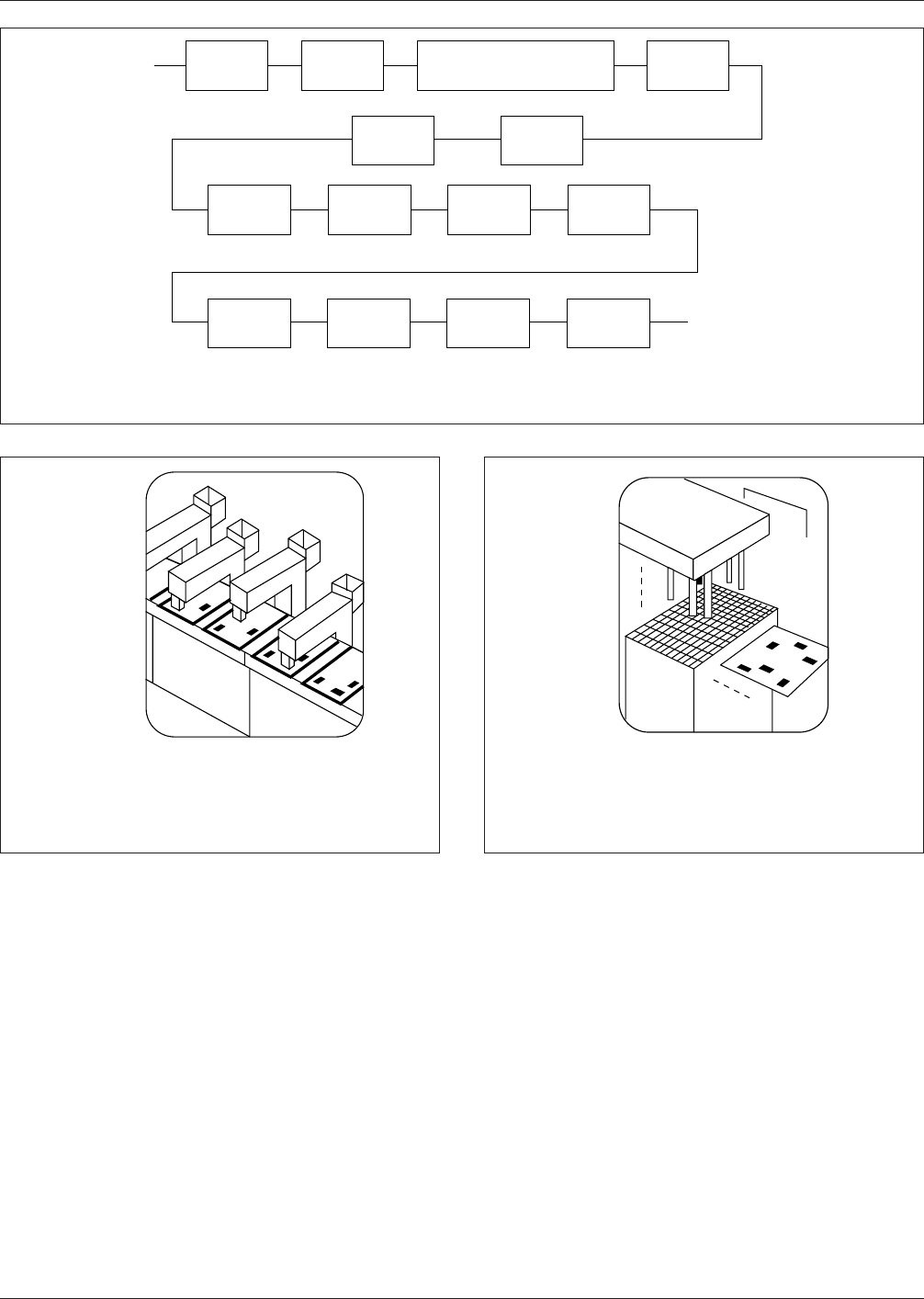
IPC-782-7-3
Figure 7–3 Typical process flow for mixed technology type 2c (complex) surface mount technology
''' '
''''
'''' '
'''
'
'
Print
Solder Paste
Dry
Paste**
Reflow
Solder
Place
Surface Mt.
Components
Clean*
Clinch Leaded
Thru-Hole
Components
Insert
Thru-Hole
Components
Invert
Board
Invert
Board
Wave
Solder
Apply
Adhesive
Cure
Adhesive
Place
Surface Mt.
Components
Clean* Test
*Optional depending on flux and cleanliness requirements. If no flux is used for solder paste
and/or wave soldering, cleaning and cleanliness test may be omitted.
**Typically used for vapor phase soldering.
IPC-782-7-4
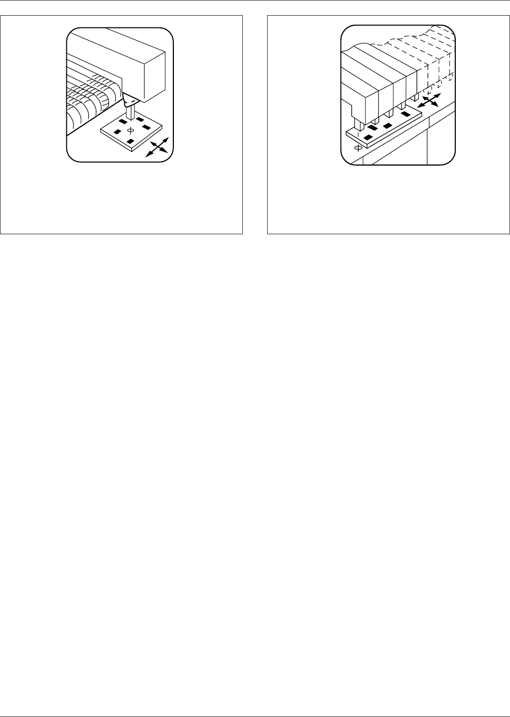
Figure 7–4 In-line placement equipment
•
Moving board/fixed head
•
Each head places one component
•
1.8 to 4.5 seconds/board
IPC-782-7-5
Figure 7–5 Simultaneous placement equipment
•
Fixed table/head
•
All components placed simultaneously
•
Seven to ten seconds/board
▼
▼
▼
December 1999 IPC-SM-782A
55
电子技术应用 www.ChinaAET.com
7.4 Soldering
Like the selection of autoplacement
machines, the soldering process selection depends upon the
type of components to be soldered and whether or not they
will be used in combination with leaded parts. For
example, if all components are surface mount types, reflow
method (vapor phase, hot air convection or infrared) may
be desirable. However, for through-hole and surface mount
combinations, in mixed technology, a combination of wave
soldering and reflow soldering may be used. No process is
best for all soldering tasks. In addition, the number of sol-
dering processes discussed in the following text are by no
means complete.
7.4.1 Wave Soldering Wave soldering is an economical
method of soldering mass terminations. There are four
main process variables that must be controlled in the wave
soldering process: preheat, fluxing, speed, and solder wave.
In preheat, allowance in the conveyer system must be made
for the thermal expansion of the board during preheating
and soldering to prevent board warpage.
In fluxing, flux density, activity and flux foam/wave height
must be closely monitored. A system must be in place to
determine when the flux activity has deteriorated and when
the old flux must be replaced and the new flux added.
Speed is the time sequence and duration of all of the steps
in soldering. By controlling the speed, more uniform and
better joints result. In controlling the conveyer speed, pre-
heating a packaging and interconnecting assembly in two
or three stages minimizes the thermal shock damage to the
assembly and improves its service life. Uniform preheating
is achieved by developing a solder schedule that specifies
preheat settings and conveyer speed for each type of board.
The solder wave is an important variable. Wave geometry
is especially important for preventing icicles and bridges
and for the proper soldering of surface mounted compo-
nents. Wave geometries include uni- and bidirectional;
single and double; rough, smooth and dead zone; oil inter-
mix, dry, and bubbled, and with or without a hot air knife.
Special solder waves just for surface mounted components
are also available.
The concern generally expressed in wave soldering of sur-
face mount devices is damage to the components when
they go through the soldering wave at 260°C [500°F]. The
maximum shift in tolerance of resistors and capacitors is
generally found to be 0.2%. This is a negligible amount
considering the part tolerance of commonly used compo-
nents is +5 to 20%. The components generally spend about
three seconds in the wave but they are designed to with-
stand soldering temperatures of 260°C [500°F] for up to 10
seconds.
In wave soldering, outgassing and solder skips are two
other main concerns. The outgassing or gas evolution
occurs on the trailing terminations of chip resistors and
capacitors. It is believed to be caused by insufficient drying
of flux and can be corrected by raising the packaging and
interconnecting assembly preheat temperature or time. The
other concern, solder skips, is caused by the shadow effect
of the part body on the trailing terminations. Orienting the
part in such a way that both terminations are soldered
simultaneously solves most shadow effect problems. Some
manufacturers use an extra land to serve as a ‘‘solder
thief’’ for active components.
The most common method for solving both outgassing and
shadow effect is by switching to the dual wave system
where the first wave is turbulent and the second wave is
IPC-782-7-6
Figure 7–6 Sequential placement equipment
•
X-Y Movement table/head
•
Components placed in succession
individually
•
0.3 to 0.8 to 4.5 seconds/board
▼
▼
IPC-782-7-7
Figure 7–7 Sequential/Simultaneous placement equipment
•
X-Y table/fixed head
•
Sequential/simultaneous firing of heads
•
0.2 seconds/component
▼
IPC-SM-782A December 1999
56
电子技术应用 www.ChinaAET.com

laminar. The turbulent wave serves to provide an adequate
amount of solder across the surface of the packaging and
interconnecting structure in order to help eliminate outgas-
sing and solder skips. The laminar wave is used to help
eliminate icicles and bridging.
7.4.2 Vapor Phase Soldering
Vapor phase soldering, also
known as condensation soldering, uses the latent heat of
vaporization of an inert liquid for soldering. The latent heat
is released as the vapor condenses on the part to be sol-
dered. The soldering temperature is constant and is con-
trolled by the type of fluid. Thus, unlike wave, IR, convec-
tion and laser soldering, vapor phase soldering does not
require control of the heat input to the solder joints or to
the board. It heats independent of the part geometry, heats
uniformly, and does not exceed the fluid boiling tempera-
ture. This process is also suitable for soldering odd-shaped
parts, flexible circuits, and pins and connectors, as well as
for reflow of tin-lead electroplate and surface mount pack-
ages. Since heating is by condensation, the rate of tempera-
ture rise depends on the mass of the part. Therefore, the
leads on the package in contact with the packaging and
interconnecting structure heat up faster than the component
body. This may lead to wicking of the solder up the lead.
All these features make vapor phase soldering an easily
automated process. It does not necessarily require the flux-
ing, preheating and soldering adjustments so critical in
other process, although prebaking and preheating is recom-
mended to remove moisture and reduce thermal shock in
the boards. Vapor phase soldering is amenable to automa-
tion but does have process related problems such as a
higher incidence of solder balls, part movement, which can
be advantageous for alignment, and damage to
temperature-sensitive parts.
Both inline and batch type systems are available. The inline
system is suitable for mass production. For low volume
production or for research and development, a batch pro-
cess is generally used. For both processes, the major disad-
vantage is price of the liquid due to vapor loss. The batch
process minimizes vapor loss by using a less expensive
secondary fluid as a blanket over the primary fluid. Vapor
loss does not change, but a cheap vapor is substituted for
expensive ones. The cooling coils are used to minimize
vapor loss.
7.4.3 IR Reflow
In infrared (IR) reflow soldering, the
radiant or convective energy is used to heat the assembly.
There are basically two types of IR reflow process—
focused (radiant) and nonfocused (convective). The latter is
proving more desirable for SMT. The focused IR radiates
heat directly on the parts and may unevenly heat assem-
blies. The heat input on the part may also be color depen-
dent. In nonfocused or diffused IR, the heating medium can
be air or an inert gas or simply the convection energy. A
gradual heating of the assembly is necessary to drive off
volatiles from the solder paste. After an appropriate time in
preheat, the assembly is raised to the reflow temperature
for soldering and then cooled.
7.4.4 Hot Air
7.4.5 Laser Reflow Soldering
Laser soldering is a rela-
tive newcomer to the soldering technology. It complements
other soldering processes rather than replacing them and,
as with in-line reflow soldering, it lends itself well to auto-
mation. It is faster than hand soldering but not as fast as
wave, vapor, IR soldering or hot air convection. Heat-
sensitive components that may be damaged in reflow pro-
cesses can be soldered by laser. Process problems include
thermal damage to surrounding areas and solder balls.
7.5 Cleaning
Cleaning of surface mount assemblies, in
general, is harder than that of conventional assemblies
because of smaller gaps between surface mount compo-
nents and the packaging and interconnecting structure and
because of the more complex solder paste residues left on
the assembly and under components. The smaller gap may
entrap flux which may cause potential reliability problems
if the packaging and interconnecting assembly is not prop-
erly cleaned. Hence the cleaning process to be used is
dependent upon the spacing between component leads,
spacing between the components and substrate, the source
of the flux residue and the soldering process.
Flux requiring solvent cleaning—synthetic or rosin based
fluxes are generally known as synthetic activated (SA),
synthetic mildly activated (SMA), rosin activated (RA) or
rosin mildly activated (RMA). Stabilized halogenated
hydrocarbon/alcohol azeotropes are the preferred solvents
for removal of synthetic and rosin based flux residues.
Flux requiring a water clean process—Companies that use
organic acid (OA) flux for reflow or wave soldering must
filter residue from water before disposal. Residues from
OA fluxes are generally removed with water.
Requirements for cleaning are dependent upon the type of
equipment as classified in Section 1.3. Some individuals do
not clean assemblies used for products; however, assembly
performance is predicated on the type of flux being used to
assist in the soldering operation.
ANSI/J-STD-001 provides characteristics of various fluxes
correlated to cleaning procedures. Users are cautioned to
thoroughly understand the corrosive or conductive proper-
ties of the flux and flux residue, before making a decision
on whether to clean or not to clean based on the end prod-
uct environment of the equipment.
7.6 Repair/Rework The repair/rework of surface mount
assemblies requires special care. Because of the small land
geometries, heat applied to the board should be minimized.
December 1999 IPC-SM-782A
57
电子技术应用 www.ChinaAET.com