Printer 710-810 v9 Interchangeable Under Screen Cleaner Module - 第11页
INTERCHANGEABLE UNDER SCREEN CLEANER MODULE REPLACEMENT PROCEDURES Chapter Issue 5, Jul 16 Technical Reference Manual 25.11 REPLACEMENT PROCE DURES Spray Ba r MANDA TOR Y T O XIC CHEMICALS MAY BE PRESENT. SAFETY GLOVES M…
INTERCHANGEABLE UNDER SCREEN CLEANER MODULE
ADJUSTMENTS AND SETTINGS
25.10 Technical Reference Manual Chapter Issue 5, Jul 16
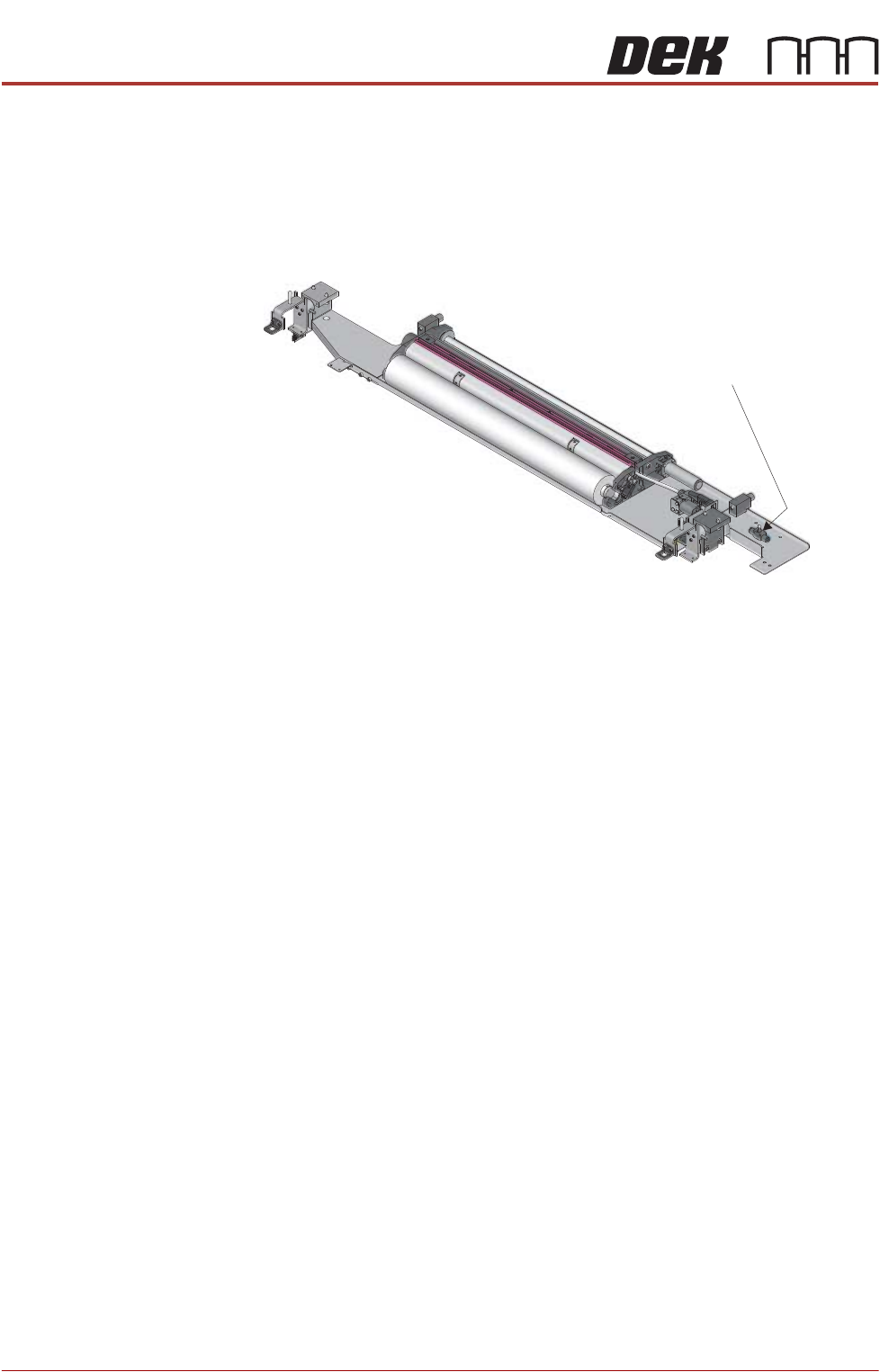
Lift Mechanism Air
Flow Controller
An in-line flow controller restricts the air flow to the cleaner lift mechanism to
prevent the cleaner from hitting the screen with excessive speed.
The air flow should not need any adjustment unless replaced. Use the following
procedure to adjust the controller:
1. Turn the thumbscrew on the lift mechanism air flow controller fully clockwise
to shut off the air supply.
2. Fit the calibration screen into the machine.
3. Select Maintenance.
4. Select Diagnostics.
5. Use Next or Previous to highlight Screen Cleaner.
6. Select Select Module.
7. Ensure ‘Toggle Dry Wipe Blade’ is highlighted.
8. Select Run Diagnost.
9. Turn the thumbscrew on the lift mechanism air flow controller anticlockwise
until the cleaner mechanism raises fully.
10. Select Run Diagnost multiple times ensuring that the lift mechanism raises
fully (without struggling or slowing).
11. Select Exit.
12. Select Exit.
13. Select Back.
Lift Mechanism Air
Flow Controller
INTERCHANGEABLE UNDER SCREEN CLEANER MODULE
REPLACEMENT PROCEDURES
Chapter Issue 5, Jul 16 Technical Reference Manual 25.11
REPLACEMENT PROCEDURES
Spray Bar
MANDATORY
TOXIC CHEMICALS MAY BE PRESENT. SAFETY GLOVES MUST BE WORN.
MANDATORY
TOXIC CHEMICALS MAY BE PRESENT. EYE PROTECTION MUST BE WORN.
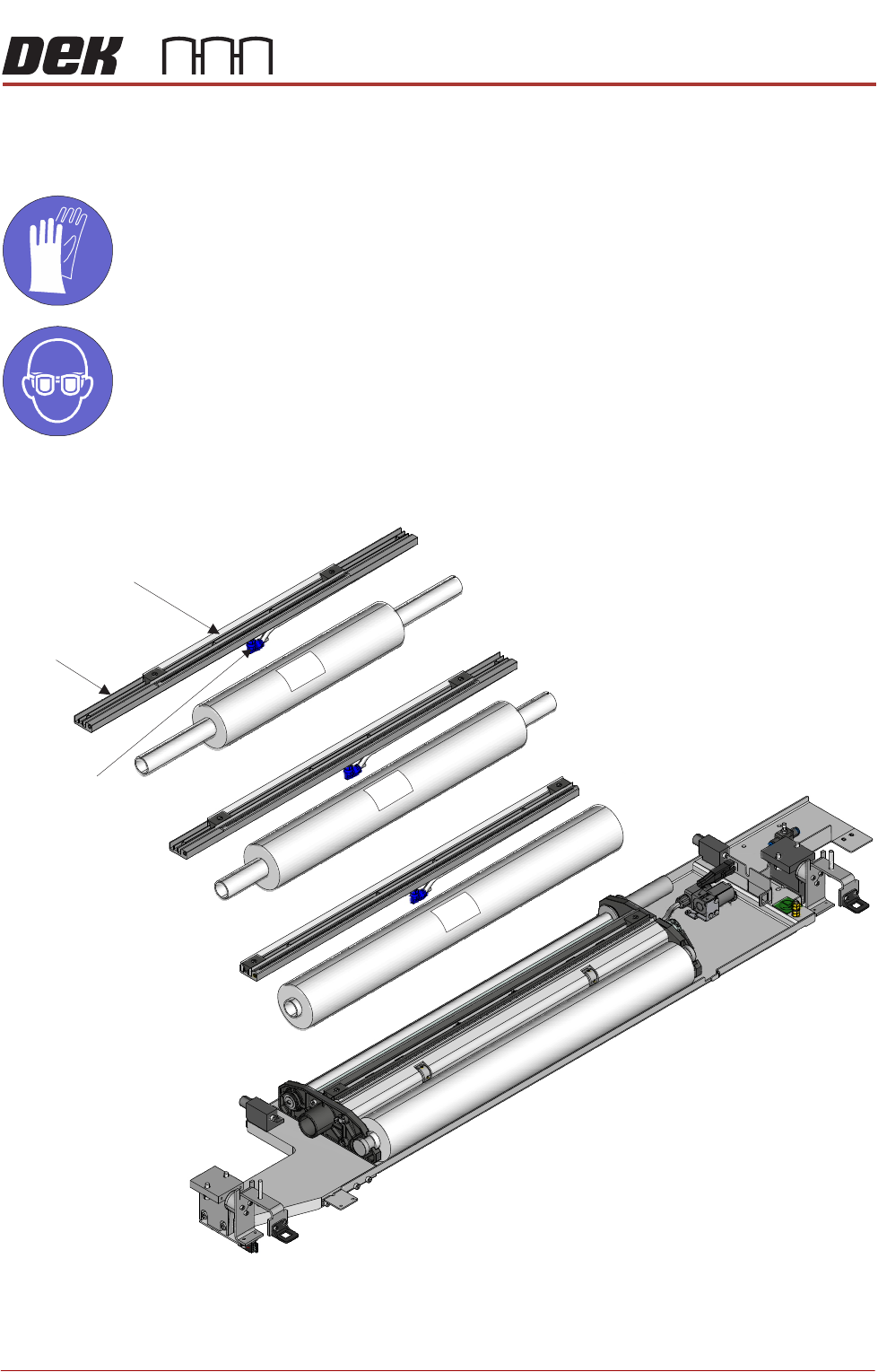
Spray bars and paper rolls are interchangeable. Three unit sizes are available.
Each spray bar is fitted to a base, underneath the base is a solvent feed tube
and a connector.
Ensure that the solvent advice at the beginning of this chapter has been read
400
300
520
Spray BarSpray Bar
Feed TubeFeed Tube
BaseBase
INTERCHANGEABLE UNDER SCREEN CLEANER MODULE
REPLACEMENT PROCEDURES
25.12 Technical Reference Manual Chapter Issue 5, Jul 16
and understood. When replacing a spray bar, ensure the tubing is unused.
To replace the spray bar proceed as follows:
1. Ensure that the printer is electrically isolated.
2. Open the printhead front cover.
3. If required, pull the USC to the front of the printer.
4. Remove the paper roll.
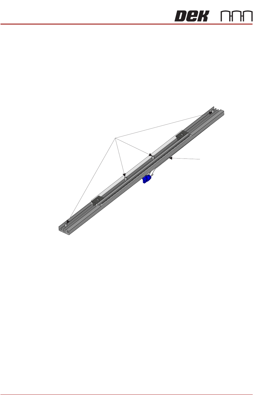
5. Locate the four M3 captive screws that attach the base to the cleaner unit.
6. Using a 2.5mm Allen key loosen the four screws.
7. Lift the spray bar mechanism away from the USC frame slowly to expose
the connector underneath the spray bar.
8. Disconnect the spray bar feed tube from the left hand side of the connector.
9. Connect the spray bar tube of the replacement unit to the solvent tube
connector.
10. Align the replacement unit in the USC frame making sure that the feed tube
is not trapped.
11. Tighten the four M3 captive screws.
12. Tighten the solvent pump connector onto the solvent pump.
13. Fit the paper roll into its holder. Tension the feed and take-up rollers with a
clean portion of paper across the spray bar.
14. Close the print head front cover.
15. Power up the printer.
16. In Diagnostics, select Screen Cleaner.
17. Select Next.
18. Select Toggle Solvent Pump.
M3 Screws (x 4)M3 Screws (x 4)
Solvent Tube
Connector
Solvent Tube
Connector