00198611-02_IM_712.1_R19-1_EN.pdf - 第67页
Station Software Version 7 12.1 (R19-1) / Installation Manual 05/2019 Edition 67 7.5 TX -Series (V1 a nd V2) Placement Machines ► When the TX placement machi nes are booted for the first t ime you must select the followi…

Station Software Version 712.1 (R19-1) / Installation Manual 05/2019 Edition
66
7.3 SX-Series Placement Machines
7.3.1 SX1/SX2 (V2) Placement Machine
► When the SX1/SX2 (V2) placement machine is booted for the first time you must select the
following options manually:
– Table configuration for both locations.
– If the manual tray Carrier SX is used, the insert frame with the fold-away tape guide
channel is required. For this, the 60 slots (outer position, fold-away tape duct) table
configuration must be selected for each location concerned. Thus, the 27x27 reject bin and
the left reject channel on the location are excluded from the configuration.
CAUTION
If this setting is not made, the component may be rejected over the tray and the Z axis
may dash hard against the tray.
► If the Coplan computer has been installed, you must additionally confirm or reject the 3-D
Coplan sensor.
7.3.2 SX+ Placement Machine
If the SX+ placement machine is to be used without gantries, this has to be configured in the auto-
configuration after the machine has been booted.
► For this, select Ignore gantries at the processing area in the machine configuration dialog.
7.3.3 SX4 Placement Machine
► When the SX4 placement machine is booted for the first time you must select the SX4 Flexible
entry for Machine frame manually in the auto-configuration, if there are tables in outer position
in processing area 2, as this is not detected automatically via sensors.
Tables in outer position are used when stationary cameras are in use.
► Otherwise you select the SX4 High Speed entry.
7.4 DX-Series Placement Machines
► When the DX placement machines are booted for the first time you must select the following
options manually:
– For C&P12 placement head: height position (altitude)
– Lamp indicators (two-colored or three-colored)
– Table position:
inner 60 tracks
outer 60 tracks
outer with 30 tracks + free location for tray or WPC
– Confirm/reject 3-D Coplan sensor
Station Software Version 712.1 (R19-1) / Installation Manual 05/2019 Edition
67
7.5 TX-Series (V1 and V2) Placement Machines
► When the TX placement machines are booted for the first time you must select the following
options manually:
– If SIPLACE JTF-ML is used, select the X-Table, multi tray feeder support option for the
JTF-ML Table 40X on Location 1.
– If no reject plate has been installed, you must disable this option explicitly.
7.6 Checking/Updating the Embedded Software
If the correct embedded SW versions are not available on the machine, the machine boot gets
interrupted.
► In this case, perform an embedded SW download.
► Start an overall reference run for the machine.
7.7 Storage Location of the Machine Files (Calibration Data etc.)
The machine-specific configuration, measurement and parameter data is stored in XML files under
C:\Sirio\Work\Individual. These XML files contain all calibration data.
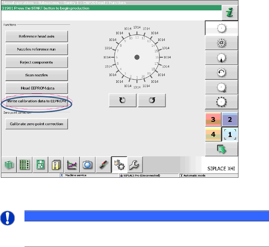
7.8 Storing Calibration Data in the EEPROM
In order to use the fast head exchange feature, the head specific calibration data has to be stored
in the EEPROM. For placement heads with no head specific calibration data stored within the
EEPROM, the available data on the station computer will be stored in the EEPROM of the
respective placement head as follows.
Requirement:
The embedded SW versions have been updated.
Station Software Version 712.1 (R19-1) / Installation Manual 05/2019 Edition
68
Figure 7-1: Storing calibration data in the EEPROM
► Perform the highlighted function for each placement head.
NOTICE
After the storing calibration data step, the message 37200 Changed heads
detected should disappear. Otherwise you must reboot the machine. If the message
still is displayed after rebooting, please inform the ASM Service.