00191413-01.pdf - 第154页
4 Data Management User Manu al Line Computer UNIX 4.6 CAD Import S oftware Version 501.xx 01/99 Issue 4 - 44 4.6.2.2 SER VICES Menu The SERVICE S menu c ontain s the foll owing men u items: - New filter This men u item i…
User Manual Line Computer UNIX 4 Data Management
Software Version 501.xx 01/99 Issue 4.6 CAD Import
4 - 43
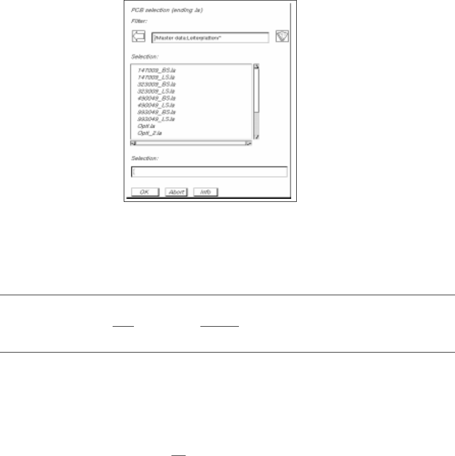
● Enter the name "xxx.la" via the keyboard and confirm with OK.
The file is saved under the name entered.
Above the display area adjacent to "Converted structure", the path and the name of the converted
structure are now displayed.
NOTE
The name may comprise max.
20 characters, including the suffix ".la". Some characters must not
be used when assigning the name; more details are contained in chapt. 2, section 2.3.
- Convert
This menu item is used to start the conversion using the specified filter.
- Discard
Any already-converted data that have not
been saved yet are discarded.
4 Data Management User Manual Line Computer UNIX
4.6 CAD Import Software Version 501.xx 01/99 Issue
4 - 44
4.6.2.2 SERVICES Menu
The SERVICES menu contains the following menu items:
- New filter
This menu item is used to define a new filter.
● Load CAD file (see section 4.6.2).
● Select the SERVICES --> New filter menu item.
The "PCB filter dialog" window opens (see Fig. 4.6.4).
CAD Import is now in the
Filter editing mode
.
The further procedure to be followed is described in section 4.6.3.
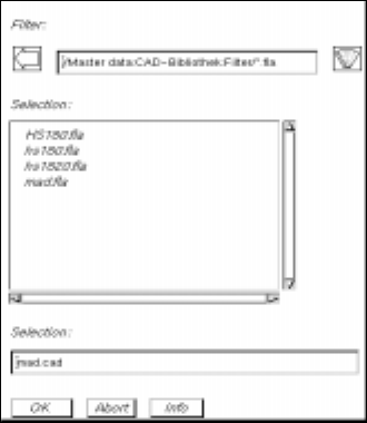
● Click on the filter selection button in the "PCB filter dialog" window.
The FSB containing the contents of the "Master data:CAD-Bibliothek:Filter" directory opens.
● Enter the name of the new filter "xx.fla" and confirm with OK (or RETURN).
The FSB closes and the name entered is transferred to the "Filter" field.
● Define the desired filter-specific data (see section 4.6.3.1) and allocate the CAD data to the posi-
tion fields (see section 4.6.3.2).
● Click on OK for the filter data to be accepted (saved). The filter dialog window closes.
- Modify filter
This menu item is used to change the data of an existing filter.
● Load CAD file (see section 4.6.2).
● Select the SERVICES --> Modify filter menu item.
The "PCB filter dialog" window opens containing the filter selected from the main window. CAD
Import is now in the
Filter editing mode
.
● Perform the required changes.
● Click on OK for the modified filter data to be accepted (saved).
A dialog box containing a verification query as to whether the "xx.fla" file is to be overwritten is dis-
played.
● Click on OK in the dialog box if the filter is to be saved under the same name (or click on Cancel
and subsequently save the filter under a new name as described above).
The dialog box and the filter dialog window are closed.
User Manual Line Computer UNIX 4 Data Management
Software Version 501.xx 01/99 Issue 4.6 CAD Import
4 - 45
- CAD data
This menu item is used to return to the display of the CAD data if the graphical display of the deter-
mined PCB structure is active (see Fig. 4.6.2).
● Select the SERVICES --> CAD data menu item.
The display is switched back to the CAD data display (see Fig. 4.6.1).
- Graphical data
Following the conversion, it is possible to display the determined PCB structure graphically.
To obtain a clearer display of the PCB, various display options for displaying the graphical elements
can be selected from the setting area. It is possible, for example, to display only placement positions
in the vie area if only these are required. The procedure to be followed is identical to the procedure in
the PCB Editor (graphic mode) and is described in detail in chapt. 8, section 8.1.3.4.
● Select the SERVICES --> Graphical data menu item.
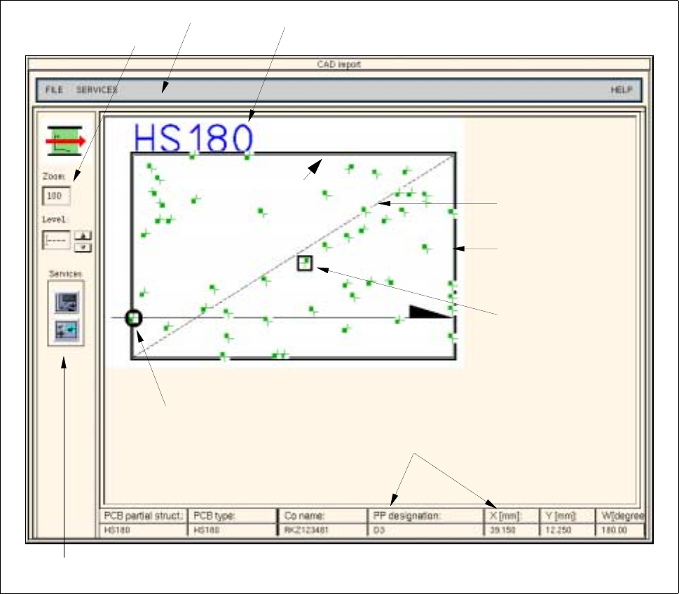
The main window of CAD Import is switched to the graphical display mode (see Fig. 4.6.2).
Fig. 4.6.2 "CAD-Import" Main Window (Display of the Graphical Data)
PCB zero point
Setting area
Menu bar
Outline of PCB
(cluster size)
Offset vector
Name of PCB structure
Editing field
for zooming
Selected placement
position
Data of the selected
placement position