00191413-01.pdf - 第159页
User Manual Line Computer UNIX 4 Data Management Software Version 501.xx 01/99 Issue 4.6 CAD Import 4 - 49 4.6.3 Filter Editing Mode In the filte r editing mode of C AD Import, e xisting filters ca n be modi fied or new …
4 Data Management User Manual Line Computer UNIX
4.6 CAD Import Software Version 501.xx 01/99 Issue
4 - 48
NOTE
Clicking once more on a selected line using the left
mouse button will cancel the selection of the line.
Clicking on a selected line using the right
mouse button causes the entire selection to be canceled
again.
If several consecutive lines are to be selected, click on the first line of the group of lines to be selected
by clicking the left mouse button, hold down the SHIFT key while selecting the last line by a click with
the left mouse button. Every line between the two will be highlighted.
● Click on the icon in the command area.
Conversion is started using the selected filter.
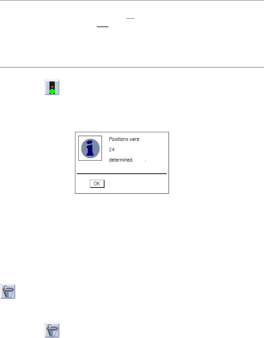
After the conversion process has been successfully completed, the following dialog box opens
displaying the number of converted data records.
If the conversion could not be completed successfully, a dialog box containing a corresponding
message is displayed.
● Close the dialog box by choosing OK.
For reviewing purposes, the placement positions determined can now be displayed graphically
(see Fig. 4.6.2), or the cluster data can be edited in the "Adapt cluster data" window (see Fig.
4.6.3).
● Save the converted structure (see section 4.6.2.1).
- (Discard)
Clicking on this icon causes the converted data (not saved yet) to be discarded, and the conversion of
the current CAD file can be restarted.
● Click on the icon in the command area.
The converted data are discarded.
User Manual Line Computer UNIX 4 Data Management
Software Version 501.xx 01/99 Issue 4.6 CAD Import
4 - 49
4.6.3 Filter Editing Mode
In the filter editing mode of CAD Import, existing filters can be modified or new filters be created. In either case
this is accomplished on the basis of the currently used CAD file. The filters are not bound to the CAD file by
means of which they were created, but they can be applied to all other CAD files whose data structure matches
that of the filter.
● Open the "PCB filter dialog" window by means of the "SERVICES" menu
(see section 4.6.2.2).
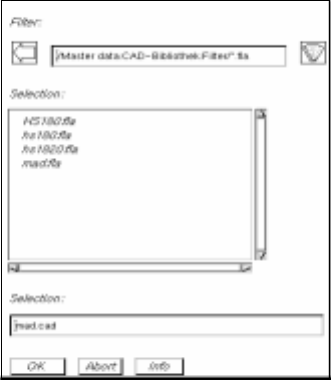
● Click on the "PCB filter dialog" filter selection button (see Fig. 4.6.4).
The FSB containing the file selection of all already-defined PP filters (*.fla) opens.
● Select the filter "xx.fla" by double-clicking, or enter new name on the keyboard and confirm with
OK (or RETURN).
The FSB closes and the name of the filter is transferred to the "Filter" field.
This is the name under which the subsequently determined filter definitions are saved (see
section 4.6.3.2).
4 Data Management User Manual Line Computer UNIX
4.6 CAD Import Software Version 501.xx 01/99 Issue
4 - 50
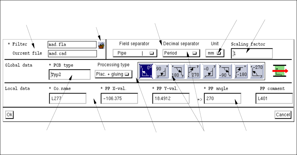
4.6.3.1 "PCB Filter Dialog" Window
Fig. 4.6.4 "PCB filter dialog" Window
The "PCB filter dialog" is subdivided into several areas. The individual areas contain selection fields (including
buttons or icons), editing fields and position fields for the definition of PP filters.
Basic Filter Data
The filter is or was created on the basis of these data.
- * Filter
This field contains the name of the currently set filter. The field is empty if no name has been assigned
to the new filter yet.
Clicking on the filter selection button causes the FSB containing the file selection of the already-
defined filters to be opened. In this FSB the name is entered under which the completely defined filter
is to be saved.
- Current file
This field contains the name of the current CAD file.
- Filter settings
The values to be set at this point are so-called fixed values. They are determined during the filter defi-
nition in accordance with the structure of the CAD file.
"Filter setting"
area
Filter selection
button
"Basic filter data"
area
"Global data"
area
"Local data"
area
Button
Position field
Editing field
Editing field
Selection
fields