00191413-01.pdf - 第161页
User Manual Line Computer UNIX 4 Data Management Software Version 501.xx 01/99 Issue 4.6 CAD Import 4 - 51 Field separator The field s eparators are use d to separ ate the da ta fiel ds within a data li ne so t hat their…
4 Data Management User Manual Line Computer UNIX
4.6 CAD Import Software Version 501.xx 01/99 Issue
4 - 50
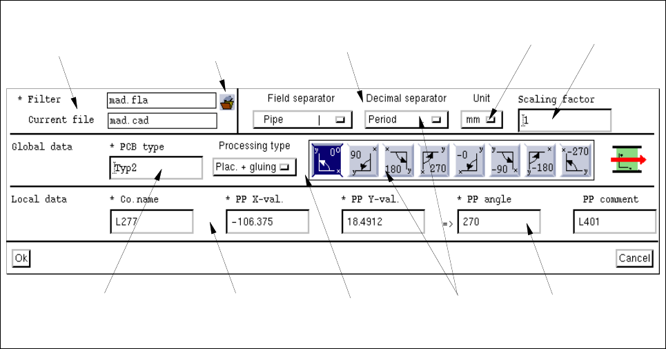
4.6.3.1 "PCB Filter Dialog" Window
Fig. 4.6.4 "PCB filter dialog" Window
The "PCB filter dialog" is subdivided into several areas. The individual areas contain selection fields (including
buttons or icons), editing fields and position fields for the definition of PP filters.
Basic Filter Data
The filter is or was created on the basis of these data.
- * Filter
This field contains the name of the currently set filter. The field is empty if no name has been assigned
to the new filter yet.
Clicking on the filter selection button causes the FSB containing the file selection of the already-
defined filters to be opened. In this FSB the name is entered under which the completely defined filter
is to be saved.
- Current file
This field contains the name of the current CAD file.
- Filter settings
The values to be set at this point are so-called fixed values. They are determined during the filter defi-
nition in accordance with the structure of the CAD file.
"Filter setting"
area
Filter selection
button
"Basic filter data"
area
"Global data"
area
"Local data"
area
Button
Position field
Editing field
Editing field
Selection
fields
User Manual Line Computer UNIX 4 Data Management
Software Version 501.xx 01/99 Issue 4.6 CAD Import
4 - 51
Field separator
The field separators are used to separate the data fields within a data line so that their respective
contents can be assigned to the appropriate position fields (see section 4.6.3.2).
● Click on the button in the "Field separator" selection field and hold down the mouse button.
The popup menu containing a list of the possible field separators opens.
● Position the mouse cursor on the entry of the desired field separator and release the mouse
button.
The menu closes and the name and the symbol of the selected field separator are displayed in
the "Field separator" selection field.
Decimal separator
Here, you can set which decimal separators are to be used to specify the values for the x and y-
coordinates of the placement positions in the CAD file.
● Click on the button in the "Decimal separator" selection field and hold down the mouse button.
The popup menu containing a list of the possible decimal separators opens.
● Position the mouse cursor on the entry of the desired decimal separator and release the mouse
button.
The menu closes and the name and the symbol of the selected decimal separator are displayed
in the "Decimal separator" selection field.
Unit
Here, the unit can be set in which the values for the x and y-coordinates of the placement positions are
to be specified in the CAD file.
● Click on the button in the "Unit" selection field and hold down the mouse button.
A popup menu containing a list of the possible units opens.
● Position the mouse cursor on the entry of the desired unit and release the mouse button.
The menu closes and the name of the selected unit is displayed in the "Unit" selection field.
Scaling factor
The scaling factor serves as conversion factor for the x and y-values. It is entered if the units for the x
and y-coordinates of the placement positions are neither specified in "mm", "inches" nor "mill", but in
a different unit (e.g. pixels or
1
/
1000
mm).
● Click on the "Scaling factor" editing field and enter a value for the factor required.
Global data
The values to be set at this point are so-called fixed values. They are determined during the filter definition in
accordance with the structure of the CAD file. They are always valid for an entire PCB structure and cannot be
changed locally for a single position.
- * PCB type
The indication of a PCB type is required for the further classification of a PCB.
This entry is mandatory.
● Click on the "PCB type" editing field and enter a name for the PCB type
(max. 15 characters).
4 Data Management User Manual Line Computer UNIX
4.6 CAD Import Software Version 501.xx 01/99 Issue
4 - 52
- Processing type
At this point, you can globally specify for all components contained in the CAD the type of processing
that is to apply.
● Click on the button in the "Processing type" editing field and hold down the mouse button.
A popup menu containing a list of the possible processing types opens.
● Position the mouse cursor on the entry of the desired processing type and release the mouse
button.
The menu closes and the name of the selected processing type is displayed in the "Processing
type" selection field.
- Coordinate system
In this selection field the different coordinate systems are symbolized by icons. They can be used to
set the position of the coordinate system of the CAD data in relation to the coordinate system of the
machine, with respect to the direction of PCB travel.
The first four icons (coordinate systems) refer to the normal position of all placement positions, i.e. the
assembly of the top side of the PCB.
The remaining four icons (coordinate systems) are required in case the CAD data are mirrored (coor-
dinate system in counterclockwise direction). This is the case, for instance, if the placement positions
on the bottom side of the PCB were described on the basis of the coordinate system of the top side of
the PCB. If coordinate systems are mirrored (- 0°, - 90°, -180° or - 270°) all angles of the placement
positions will be rotated by 180°.
● Click on the icon representing the coordinate system to be set.
Local data
In the Local data the actual structure of the CAD data is described by assigning data fields to position fields.
Each position field whose name is preceded by an asterisk * must be assigned a data field. Any allocation to
the "PP comment" position field is optional.
- * Co.name
This position field is assigned the component name from the CAD file.
- * PP X-val.
This position field is assigned the x-coordinate of the placement position from the CAD file.
- * PP Y-val.
This position field is assigned the y-coordinate of the placement position from the CAD file.
- * PP angle
This position field is assigned the rotational angle of the placement position from the CAD file.
- PP comment
This position field can be assigned the comment relating to the placement position form the CAD file.