00191413-01.pdf - 第169页
User Manual Line Computer UNIX 5 Product / Component Software Version 501.xx 01/99 Issue 5.1 Component Editor 5 - 3 Me nu ba r The menu ba r contai ns the "FILE", "SE RVICES ", "OPT IONS" an…
5 Product / Component User Manual Line Computer UNIX
5.1 Component Editor Software Version 501.xx 01/99 Issue
5 - 2
5.1.2 Main Window of Component Editor
The areas of the main window and their functions are explained in the following.
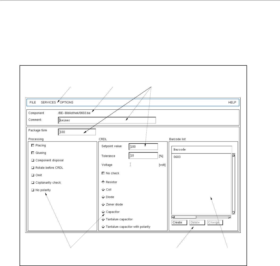
Fig. 5.1.1 Main Window "Component Editor"
The main window is subdivided as follows:
- Menu bar
- Title bar
- Editing fields
- Selection fields
- Command area
- Display area
menu bar
title bar
editing fields
selection fields command area display area

User Manual Line Computer UNIX 5 Product / Component
Software Version 501.xx 01/99 Issue 5.1 Component Editor
5 - 3
Menu bar
The menu bar contains the "FILE", "SERVICES", "OPTIONS" and "HELP" menus.
A complete description of the "SERVICES" menu is contained in section 5.1.2.1.
NOTE
Since the functions and operation of the "FILE", "OPTIONS" and "HELP" menus are similar to those in
other application programs of the line computer, they are described comprehensively in chapt. 2.
Title bar
The title bar displays the directory in which the selected component (or the component file) is contained and
the name of the component.
Editing fields (see section 5.1.2.3)
In the editing fields below the title bar an optional comment and the package form no. corresponding
to the particular component type can be entered.
The setpoint (nominal) value, the tolerance and the voltage value (only in the case of tantalum capacitors) of
the component for the CRDL test are entered in the appropriate editing fields in the selection field "CRDL".
Selection fields (see section 5.1.2.2)
In the selection field "Processing" (left portion of the main window) the type of processing for the particular
component is defined.
The selection field "CRDL" (right portion of the main window) serves to define the type of a particular component
to (e.g. component type "diode"). By selecting the component type the corresponding CRDL test will be
performed for the particular component (e.g. a voltage check in the case of a diode).
Command area (see section 5.1.2.4)
When activated, the commands in this area can be used to create a total of 6 barcodes for the current component,
or to delete or change already existing barcodes.
Display Area
All barcodes created for the current component are displayed in the view area.

5 Product / Component User Manual Line Computer UNIX
5.1 Component Editor Software Version 501.xx 01/99 Issue
5 - 4
5.1.2.1 SERVICES menu
The menu SERVICES only contains the "Starting the Package Form Editor" function.
- Starting the Package Form Editor
To define a package form for the current component or to edit the already-existing package form.
NOTE
If a new component has been defined, the Package Form Editor can only be started after the
component has been saved.
Moreover, in the "Package form" editing field a number for the package form number must be entered.
● Select the Start Package Form Editor menu item.
If no package form has been defined yet for the current component, the window for the selection
of the package form type appears (see chapt. 6).
● Click on the desired package form type.
The selection window is closed, and the main window of the Package Form Editor (see chapt. 6)
containing the selected package form type is displayed.
NOTE
If a package form had already been defined for the current component, the main window of the
Package Form Editor (see chapt. 6) is displayed right away containing the respective package
form type.