00191413-01.pdf - 第173页
User Manual Line Computer UNIX 5 Product / Component Software Version 501.xx 01/99 Issue 5.1 Component Editor 5 - 7 5.1.2.3 Component Editor Editing Fields Edit ing fi elds - Com ment Any com ment you m ay wish t o enter…

5 Product / Component User Manual Line Computer UNIX
5.1 Component Editor Software Version 501.xx 01/99 Issue
5 - 6
Selection field "CRDL"
This selection field serves to define the type of the electrical test to be performed (using the CRDL Tester) on
the component, by selecting the component type.
The following types of CRDL testing can be selected by activating the appropriate buttons:
- No check The component is not subjected to any electrical test during
processing.
- Resistance The resistance value (mega-ohms, kilo-ohms, ohms) is tested.
- Coil The inductance (µH) of the coil is tested.
- Diode The conducting-state voltage (V) of the diode is tested.
- Zener diode The Zener voltage (V) of the diode is tested.
-
- Capacitor The capacitance (µF, nF, pF) of the capacitor is tested.
- Tantalum capacitor The capacitance (µF, nF, pF) of the tantalum capacitor is tested.
- Tantalum capacitor with polarity The capacitance (µF, nF, pF) of the polarized tantalum capacitor
is tested.
Procedure:
● Click on button adjacent to the CRDL test desired.
Whenever a different type of CRDL test is clicked on, the one previously selected is deselected.
When the button No check has been selected it can only be deselected by clicking on it a second
time.

User Manual Line Computer UNIX 5 Product / Component
Software Version 501.xx 01/99 Issue 5.1 Component Editor
5 - 7
5.1.2.3 Component Editor Editing Fields
Editing fields
- Comment Any comment you may wish to enter can be entered in
this field, e.g. type of the component. (No inverted
commas or quotation marks will be accepted).
- Package form The GF no. assigned to the particular component type
(package) is entered in this editing field (e.g. 750 for QFP44).
NOTE: The GF-number must be entered without
any suffix!
- Setpoint value The setpoint value of the component is entered using the
scientific notation, e.g.:
1E12 for 10 T (tera) = 10 000 000 000 000
1E9 for 10 G (giga) = 10 000 000 000
1E6 for 10 M (mega) = 10 000 000
10E3 for 10 K (kilo) = 10 000
10E-3 for 10 m (milli) = 0.010
10E-6 for 10 µ (micro) = 0.000010
10E-9 for 10 n (nano) = 0.000000010
10E-12 for 10 p (pico) = 0.000000000010
- Tolerance In this field the permissible deviation of the tested value
from the setpoint value is entered in % (e.g. 10 for 100kΩ
resistance).
- Voltage This field can only be edited when in the selection field
"CRDL" the component type "Tantalum capacitor" has
been selected for the current component. The operating
voltage (volts) of the tantalum capacitor is entered here.
5 Product / Component User Manual Line Computer UNIX
5.1 Component Editor Software Version 501.xx 01/99 Issue
5 - 8
5.1.2.4 Component Editor Command Area
The desired actions can be activated by means of the command buttons. The procedures for executing the
commands are described in the following:
COMMANDS
● Create
This command can be used to define a barcode for the component.
NOTE
For each component a total of 6 barcodes can be defined. Once the maximum permissible number
of barcodes for the current component has been reached, the "Create" button can no longer be
activated.
● Click on Create.
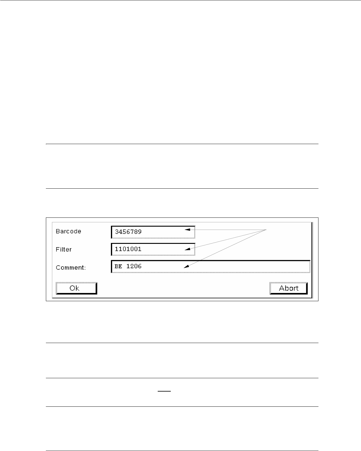
The window for the description of the new barcode is opened (see Fig. 5.1.2).
Fig. 5.1.2 Entry Window "Barcode"
● Click on editing field "Barcode", enter the desired sequence of characters and terminate the entry
by pressing RETURN.
NOTE
The barcode may comprise up to 40 characters. Valid characters are letters, numbers, points,
underscores and hyphens.
● Click on editing field "Filter", validate each character of the defined barcode (by entering 1 or 0)
and terminate your entry by pressing RETURN.
NOTE
Digit "1" stands for "valid" and digit "0" for "invalid".
The length of the filter (number of digits) must correspond to the length of the barcode (number of
characters).
editing fields