00191413-01.pdf - 第195页
User Manual Line Computer UNIX 6 Product / Package Form Software Version 501.xx 01/99 Issue 6.1 Package Form Editor 6 - 17 Opening the window for entering or changing model data ● Select d esired pin or ball by (quick ly…

6 Product / Package Form User Manual Line Computer UNIX
6.1 Package Form Editor Software Version 501.xx 01/99 Issue
6 - 16
6.1.2.6 View area - "Vision data" Screen
The current package form is graphically represented in the view area. When the dimensions are edited in the
"Nominal dimensions" and "Body" editing areas, the display is automatically updated.
-
The package (body) is drawn as a rectangle with a solid black line.
-
The two rectangles drawn with a broken black line reflect the nominal dimensions including negative
and positive tolerance values. (The nominal dimensions themselves are not displayed).
-
Created pin models are depicted as filled dark-blue rectangles in accordance with their length and
width dimensions. Their color changes depending on their state (see color explanation below).
-
Created ball models are depicted as filled dark-blue circles in accordance with their diameters. Their
color changes depending on their state.
Explanation of colors
Dark-blue pin/ball --> non-selected group for which a model is defined.
Gray-blue pin/ball --> non-selected group for which no model has been defined yet.
Dark-green pin/ball --> selected group for which a model is defined.
Light-green pin/ball --> selected group for which no model has been defined yet.
Single-click on a pin or a ball with the color
dark-blue or gray-blue --> draws a black frame around the group to which the clicked-on object
belongs.
The pins/balls contained in the selected group are displayed in
dark-green or light-green.
All pins/balls contained in the non-selected groups for which the same
model was defined, are displayed in dark-green.
Single-click on a pin or a ball with the color
dark-green or light-green --> reverses the selection
NOTE
For the windows required for changing group or model data to open, the clicking sequence described below
must be observed.
Opening the window for changing group data
●
Single-click on any pin (see Fig. 6.1.1) or ball (see Fig. 6.1.3) of the desired group.
The whole group is highlighted.
●
Select pin or ball once more by (quickly) double-clicking.
The window for editing the group data is opened (see Fig. 6.1.20).

User Manual Line Computer UNIX 6 Product / Package Form
Software Version 501.xx 01/99 Issue 6.1 Package Form Editor
6 - 17
Opening the window for entering or changing model data
●
Select desired pin or ball by (quickly) double-clicking.
The window for editing the model data is opened (see Fig. 6.1.21 and Fig. 6.1.26).
NOTE
The window for editing the group or model data can also be opened using the commands "Group"
or "Pin/Ball" (see section 6.1.2.4).
6 Product / Package Form User Manual Line Computer UNIX
6.1 Package Form Editor Software Version 501.xx 01/99 Issue
6 - 18
6.1.2.7 Package Form Editor Command Area - "Handling data" Screen
In the command area (see Fig. 6.1.4) two different tools can be selected from (nozzle or sensor type) that can
be created or deleted by means of the corresponding commands. The desired tool type desired is selected by
clicking on the button adjacent to its name.
COMMANDS
The procedures to be followed for the execution of the commands are described in the following.
-
Create
This command can be used to create the nozzles and sensor system types required for the current
package form.
●
Activate the button of the desired tool type.
●
Click on
Create
.
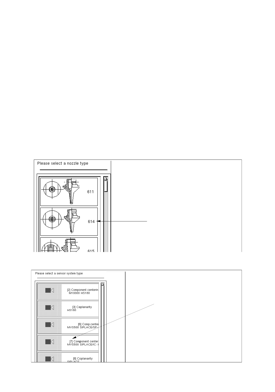
The selection window containing a list of all defined types of the selected tool type is opened.
Fig. 6.1.7 Selection Window of the "Nozzle Type"
Fig. 6.1.8 Selection Window of the "Sensor Type"
type 6xx nozzle
number of the
sensor s
y
stem t
y
pe