00191413-01.pdf - 第203页
User Manual Line Computer UNIX 6 Product / Package Form Software Version 501.xx 01/99 Issue 6.1 Package Form Editor 6 - 25 Minimum and Maximum Axis Acceleration Values Machine Type Head Type Nozzle Type Acceleration Valu…

6 Product / Package Form User Manual Line Computer UNIX
6.1 Package Form Editor Software Version 501.xx 01/99 Issue
6 - 24
General Notes Relating to the Buttons in the View Area
-
Appropriate buttons in the view area allow the
"
Acceleration
"
special handling option for selected nozzles
to be activated or deactivated, respectively.
-
If the button for the special handling procedure was activated, minimum (35%), medium (70%) or maxi-
mum ( 100%) acceleration of the axes can be selected for each individual nozzle of the 4xx, 7xx and 8xx
types on machine types 80S-20/23/HS-50 and 80F
4
/F
5
using the corresponding arrow buttons.
The desired percentage can also be entered directly into the adjacent editing field.
After the value has been entered, the RETURN key must be pressed or a different field be clicked for the
value to be accepted.
For nozzle types 2xx and 6xx on machine types 80S-15, 80F3 and HS-180, only minimum (35%) or maxi-
mum (100%) acceleration can be selected. The settings are always valid for all nozzles of a given type.
-
Axis-specific settings can be selected in the appropriate dialog boxes (see Fig. 6.1.10 and Fig. 6.1.11) when
the button
"
>>
"
assigned to the corresponding nozzle is clicked on.
6.1.2.9 Settings for the "Acceleration" Special Handling
To be able to also transport and deposit large components (e.g. PLCC's 84) safely, the acceleration of the x,
y, z and d(dp) axes can be reduces as required by means of the special handling option.
On machine types SIPLACE 80S-15, 80F3 and HS-180 it is possible to reduce the acceleration of the individual
axes to 35% for nozzle types 2xx and 6xx.
On machine types SIPLACE 80S-20/23/HS-50 and 80F
4
/F
5
it is possible to select axis-specific accelerations
for each individual nozzle of the types 4xx, 7xx and 8xx.
Due to the fact that 4xx type nozzles can be used on machine types SIPLACE 80F3 and
80F
4
/F
5
, it is possible
to enter axis-specific acceleration values. On machine type SIPLACE 80F3, however, the acceleration is
automatically reduced to 35% if full acceleration (100%) is not selected.
User Manual Line Computer UNIX 6 Product / Package Form
Software Version 501.xx 01/99 Issue 6.1 Package Form Editor
6 - 25
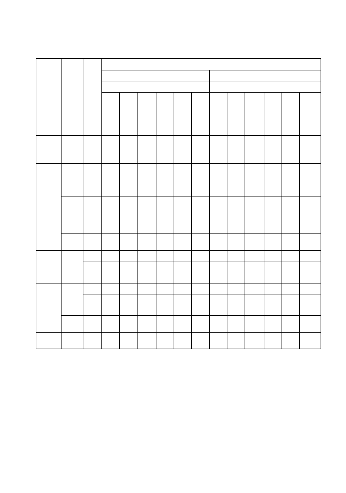
Minimum and Maximum Axis Acceleration Values
Machine Type
Head Type
Nozzle Type
Acceleration Values
Minimum Acceleration Maximum Acceleration
Axis Axis
x
g
y
g
Star
g
z
↑
g
z
↓
g
dp
(d)
rad/
s
2
x
g
y
g
Star
g
z
↑
g
z
↓
g
dp
(d)
rad/
s
2
S-20
S-23
HS-50
12-
noz.
RV-
Head
7xx
0,1 0,1 0,1 0,1 0,1 0,1 4 4 5,8 5,3 5,3 3100
F4
12-
noz.
RV-
Head
7xx
0,1 0,1 0,1 0,1 0,1 0,1 4 4 5,8 5,3 5,3 3100
6-
noz.
RV-
Head
7xx /
8xx
0,1 0,1 0,1 0,1 0,1 0,1 4 4 5,2 5,3 5,3 1282
IC-
Head
4xx
0,1 0,1 0,1 0,1 0,1 0,1 4 4 -- 1,3 1,3 641
S15
12-
noz.
RV-
Head
3xx
-- -- -- -- -- -- -- -- -- -- -- --
6xx
-- -- -- 35% 35% 35% -- -- -- 5,3 5,3 3100
F3
12-
noz.
RV-
Head
3xx
-- -- -- -- -- -- -- -- -- -- -- --
6xx
-- -- -- 35% 35% 35% -- -- -- 5,3 5,3 3100
IC-
Head
4xx
35% 35% -- 35% 35% 35% 4 4 -- 1,3 1,3 641
HS-180 IC-
Head
2xx
35% 35% -- 35% 35% 35% 4 4 -- 1,3 1,3 641
Tab. 6.1 - 1 Acceleration Values
6 Product / Package Form User Manual Line Computer UNIX
6.1 Package Form Editor Software Version 501.xx 01/99 Issue
6 - 26
Special Handling for Nozzle Types 2xx, 4xx
(IC-Head F3)
or 6xx
Special handling during the pick-up, centering and placement processes can be defined for the nozzle types
mentioned above, i.e. the acceleration of the selected axes (or processes) is reduced to 35%
.
Procedure (Example for Nozzle Type 2xx):
●
In the view area (see Fig. 6.1.9) activate the "Special handling" button adjacent to the nozzle of
the desired type.
●
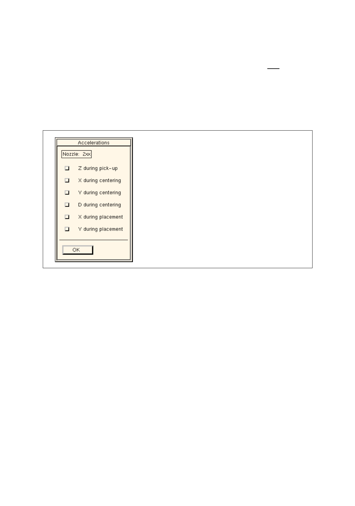
Click on the ">>" button. The following dialog box opens.
Fig. 6.1.10 Dialog Box for Selecting the "Acceleration" Special Handling Option (Example: Nozzle Type 2xx)
Setting possibilities
Z during pick-up
(not for 6xx) reduced acceleration of the z-axis of the RV or IC head
on picking up the component from the pick-up position
X during centering
(not for 6xx) reduced acceleration of the X-axis during transporting the
component from the camera to the placement position by means
of the IC head
Y during centering
(not for 6xx) reduced acceleration of the Y-axis during transporting the
component from the camera to the placement position by means
of the IC head
D during centering
reduced acceleration of the dp1- and dp2-axes of the RV head
and of the d-axis of the IC head upon centering the component
X during placement
(not for 6xx) reduced acceleration of the X-axis during transporting the
component from the pick-up to the placement position by means
of the RV head
reduced acceleration of the X-axis during transporting the
component from the IC camera to the placement position by
means of the IC head